PWM overmodulation method based on optimized quasi sine flat modulating wave

A modulated wave and overmodulated technology, which is applied in the direction of output power conversion device, electrical components, AC power input to DC power output, etc., can solve the difficulty of occupying more processor resources and CPU running time, and PWM calculation program programming Increased size, complex program structure, etc.

Active Publication Date: 2014-01-01
FUZHOU UNIV
View PDF3 Cites 19 Cited by
  • Summary
  • Abstract
  • Description
  • Claims
  • Application Information

AI Technical Summary

Problems solved by technology

[0022] The content of the above algorithm makes the composition of SVPWM overmodulation technology quite complicated
When the DSP device is used to implement, the programming difficulty of the PWM calculation program is increased, the program structure is complex, and more processor resources and CPU running time are required, which is unfavorable to the timeliness and accuracy of the calculation.

Method used


Image

  • PWM overmodulation method based on optimized quasi sine flat modulating wave
  • PWM overmodulation method based on optimized quasi sine flat modulating wave
  • PWM overmodulation method based on optimized quasi sine flat modulating wave

Examples


Embodiment Construction
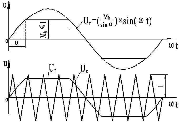
[0060] The basic idea of ​​the present invention is to construct a new type of modulated wave with larger fundamental wave components and make the contained harmonic components as small as possible. The modulation wave is as image 3 As shown, the modulation wave U r The waveform obtained after cutting off the top from the sine wave, the middle part is a flat top wave, and the two waists are sine waves; its mathematical description is as follows:

[0061] U r = M h sin α sin ( ωt ) 0 ≤ ωt ≤ α ...


PUM


Abstract

The invention relates to a PWM overmodulation method based on an optimized quasi sine flat modulating wave. The method is characterized in that firstly, one quasi sine flat wave is established to serve as the modulating wave, a triangular carrier wave is modulated, and then a three-phase PWM overmodulation algorithm is adopted for overmodulation. According to the method, three-phase PWM is generated by adopting the triangular carrier wave, the largest output linear voltage fundamental wave amplitude value of the three-phase PWM in a linear area is 19% higher than that of SPWM, and therefore the direct-current voltage use ratio is remarkably improved.

Description

technical field [0001] The invention relates to an optimized quasi-sine flat-top modulation wave PWM overmodulation method. Background technique [0002] PWM overmodulation technology refers to a PWM technology that maximizes the utilization rate of the DC bus voltage and its maximum output reaches the square wave mode. At present, the PWM over-modulation technology that has been studied more is the SVPWM (SpaceVectorPWM Space Voltage Vector Pulse Width Modulation) over-modulation technology. [0003] The modulation range of the entire SVPWM is divided into a linear region and an overmodulation region, and the corresponding PWM algorithm is described as follows. [0004] 1. Linear area: SVPWM divides the vector space into 6 sectors through 6 basic space voltage vectors, such as figure 1 shown. The basic vector labels are in order of abc, 1 means that the upper bridge arm of this phase is open, and 0 means that the lower bridge arm of this phase is open. Uref represents t...

Claims


Application Information

Patent Timeline
Patent Type & Authority Applications(China)
IPC IPC(8): H02M7/5387
Inventor 王榕生
Owner FUZHOU UNIV
Why Eureka
Try Eureka