
Syringe putter with o-type ring rubber plug

A technology for a syringe and a rubber stopper is applied in the field of a syringe push rod with an O-ring rubber stopper, which can solve the problem of the large radius of the circular arc of the tip of the rubber stopper sealing ring, the large contact area between the rubber stopper and the liquid medicine, and the tip of the sealing ring ring falling off. Difficulty in molds and other problems, to achieve the effects of product safety, reduction of raw material costs, and simple structure

Inactive Publication Date: 2014-01-08
HUAIAN CITY HENGCHUN MEDICAL PROD
View PDF6 Cites 2 Cited by
  • Summary
  • Abstract
  • Description
  • Claims
  • Application Information

AI Technical Summary

Problems solved by technology

[0002] The existing rubber plug installed at the front end of the syringe push rod includes the rubber plug body and the cavity for connecting the syringe push rod. The rubber plug and the push rod are interference fit, and most of them are provided with two seals on the rubber plug body. Ring structure, that is, two sealing rings on the upper edge and the bottom edge. The arc radius at the tip of the sealing ring of this structure is relatively large, and the angle between the tip of the sealing ring is made greater than 90 degrees due to the difficulty of demoulding. The protrusion is not obvious, resulting in large push-pull friction resistance of the push rod, poor sealing due to poor elasticity of the material, etc.
[0003] Moreover, the contact area between the rubber plug and the liquid medicine is large, which will cause certain pollution to the liquid medicine

Method used


Image

  • Syringe putter with o-type ring rubber plug
  • Syringe putter with o-type ring rubber plug

Examples


Embodiment Construction

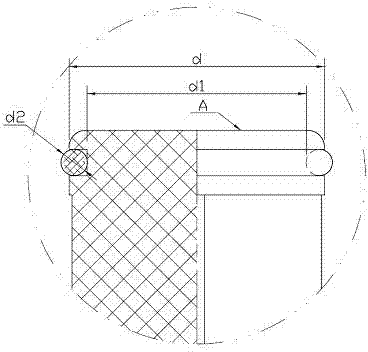
[0015] Such as figure 1 , 2 As shown, it includes an o-ring rubber plug 1 and a push rod body 2. The lower part of the push rod body 2 is provided with a pusher 21, and the upper part of the push rod body 2 is provided with a push rod head 22. A push-pull ring 221 is formed on the push rod head 22. The feature is: the push-pull ring 221 is provided with a groove 222 for installing the o-ring rubber plug 1 , and the groove 222 is located in the middle of the push-pull ring 221 .

[0016] Wherein, the diameter d of the push-pull ring 221 is slightly smaller than the inner diameter of the syringe barrel.

[0017] Wherein, the top surface A of the push-pull ring 221 is a plane or a curved surface, depending on the top shape of the syringe barrel.

[0018] Wherein, the groove 222 is square or arc-shaped, the inner diameter of the groove 222 is equal to the inner diameter d1 of the o-ring rubber plug 1, the width of the groove 222 is equal to the wire diameter d2 of the o-ring rub...


PUM


Abstract

The invention discloses a syringe putter with an o-type ring rubber plug. The syringe putter includes the o-type ring rubber plug (1) and a putter body (2); the lower portion of the putter body (2) is provided with a pressing handle (21), the upper portion of the putter body (2) is provided with a putter head (22), and a push-pull ring (221) is formed on the putter head (22). The syringe putter is characterized in that the push-pull ring (221) is provided with a groove (222) used for installing the o-type ring rubber plug (1), and the groove (222) is located in the middle of the push-pull ring (221). The syringe putter is easy to push and pull, good in sealing performance, low in manufacturing cost and safer to use.

Description

technical field [0001] The invention relates to a syringe push rod, in particular to a syringe push rod with an ○-ring rubber stopper. Background technique [0002] The existing rubber plug installed at the front end of the syringe push rod includes the rubber plug body and the cavity for connecting the syringe push rod. The rubber plug and the push rod are interference fit, and most of them are provided with two seals on the rubber plug body. Ring structure, that is, two sealing rings on the upper edge and the bottom edge. The arc radius at the tip of the sealing ring of this structure is relatively large, and the angle between the tip of the sealing ring is made greater than 90 degrees due to the difficulty of demoulding. The protrusion is not obvious, resulting in large push-pull friction resistance of the push rod, poor sealing due to poor elasticity of the material, etc. [0003] Moreover, the contact area between the rubber plug and the liquid medicine is large, which...

Claims


Application Information

Patent Timeline
Patent Type & Authority Applications(China)
IPC IPC(8): A61M5/315
Inventor 邹小明
Owner HUAIAN CITY HENGCHUN MEDICAL PROD
Learn More