A jig for processing the outer wall of thin-walled sleeve parts without a through hole and its use method

A technology of thin-walled sleeves and parts, which is applied in the field of mechanical processing, can solve problems such as processing failure, reduced precision, and unstable clamping, and achieve the effects of reducing processing costs, improving production efficiency, and enhancing clamping effects

Active Publication Date: 2017-01-18
贵州凯星液力传动机械有限公司
View PDF8 Cites 1 Cited by
  • Summary
  • Abstract
  • Description
  • Claims
  • Application Information

AI Technical Summary

Problems solved by technology

This scheme is to realize the clamping of sleeves from the inside of the sleeve, that is, to realize the clamping requirements of rough turning. Although this scheme can realize effective clamping, its fixed position is only at the open end of the sleeve part. The inner bottom of the part cannot be fixed, and the clamping of the lathe caliper will be unstable when it rotates at high speed. The part may rotate and deviate, and deformation will occur during the processing, which will lead to processing failure or reduced precision, resulting in defective or scrap products , for the sleeve that requires high precision, it cannot be processed

Method used


Image

  • A jig for processing the outer wall of thin-walled sleeve parts without a through hole and its use method
  • A jig for processing the outer wall of thin-walled sleeve parts without a through hole and its use method
  • A jig for processing the outer wall of thin-walled sleeve parts without a through hole and its use method

Examples


Embodiment

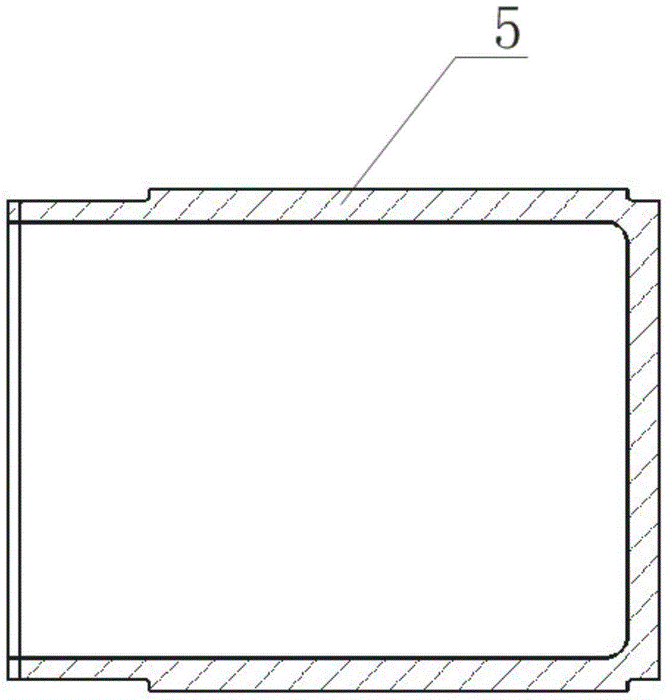
[0039] Embodiment: before use, need processing such as figure 1 For the parts shown in the figure, first use the three-jaw chuck on the lathe or grinder to clamp the upper clamping position of the mandrel 1, and calibrate the mandrel 1 so that the outer conical surface of the mandrel 1 is coaxial with the machine tool spindle.

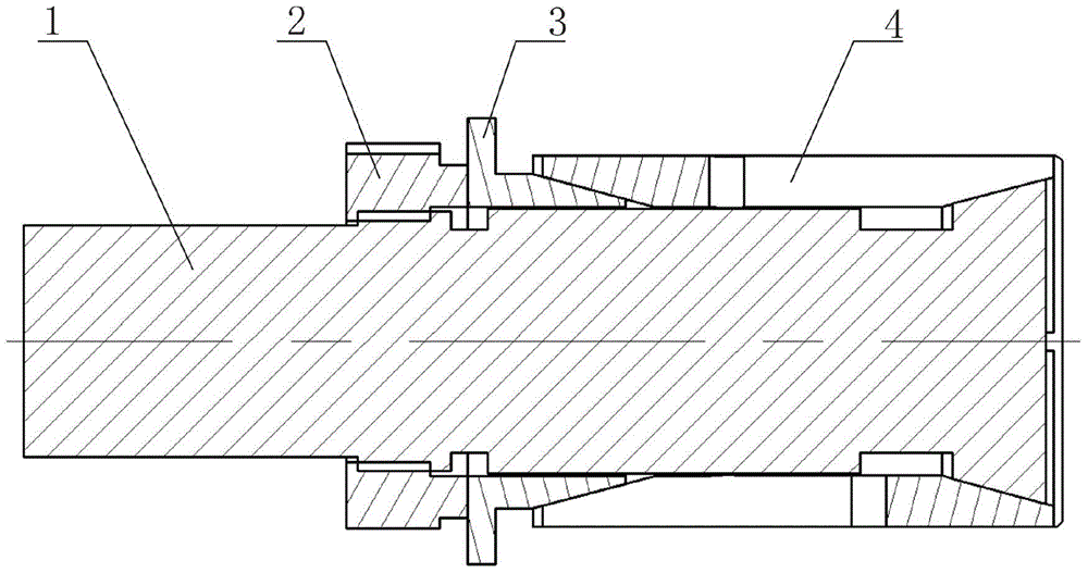
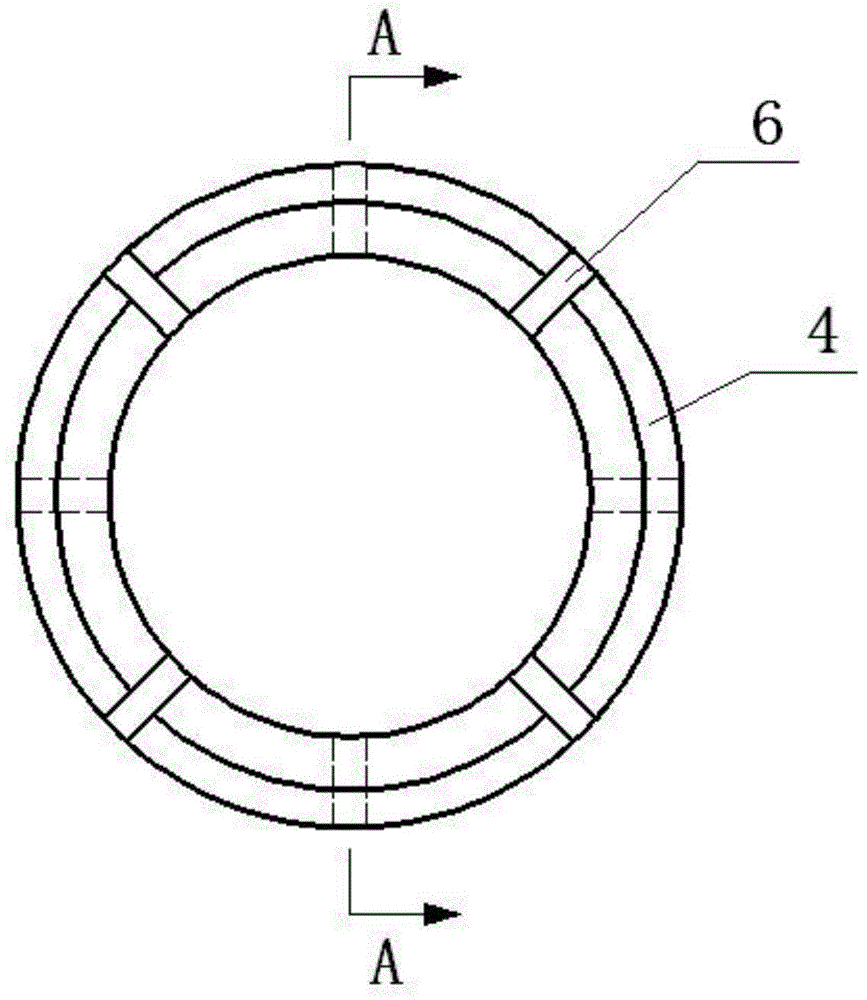
[0040] When used, it will be as figure 1 The opening of the part 5 shown is placed on the elastic collet 4 to the left and is as follows: Figure 5 In the state shown, make the inner bottom of the part 5 fit closely with the right end surface of the elastic collet 4, then turn the fastening nut 2 to the right to make the fastening nut 2 move axially to the right, and then push the taper sleeve 3 to Slide in the elastic jacket 4, and at the same time pull the end of the mandrel 1 to slide in the elastic jacket 4, due to the taper fit between the tapered sleeve 3 and the elastic jacket 4, the mandrel 1 and the elastic jacket taper fit, and the elastic j...


PUM


Abstract

The invention discloses a machining clamp for the outer wall of a blind-hole thin-wall sleeve part and a using method of the machining clamp. The clamp comprises a core shaft and a fastening nut connected on the core shaft through threads. The core shaft is sleeved with an elastic clamping sleeve, the elastic clamping sleeve is overall cylindrical, cones with the large outsides and the small insides are arranged at the two ends of the elastic clamping sleeve, a conical surface is arranged at the tail end of the core shaft, the tail end of the core shaft is matched with the elastic clamping sleeve, the core shaft is further sleeved with a taper sleeve, the taper sleeve is arranged between the fastening nut and the elastic clamping sleeve, and the conical surface of the tapper sleeve is arranged in the elastic clamping sleeve. The design of the elastic clamping sleeve with two expansile ends is adopted in the clamp, the inner diameter of the part is centered when the elastic clamping sleeve expands, the opening end and the inner bottom end of the part are simultaneously clamped, the function of bidirectional clamping is achieved, then the locating and clamping effect of the clamp is enhanced, the clamping and machining deformation of the external circle of the thin-wall sleeve part can be effectively prevented when finish machining is carried out on a lathe and a grinding machine, machining quality is guaranteed and improved, and therefore production efficiency is improved, and machining cost is lowered.

Description

technical field [0001] The invention relates to a jig for processing the outer wall of sleeve parts and a method for using the same, in particular to a jig for processing the outer wall of thin-walled sleeve parts with no holes and a method for using the same, belonging to the technical field of mechanical processing. Background technique [0002] In machining, such as figure 1 The inner hole of this kind of thin-walled sleeve parts shown is a non-through hole, and the requirements for the dimensional accuracy, shape and position tolerance and surface roughness of the parts are relatively high. The traditional processing method of this kind of parts is generally lathe processing. After the rough machining on the lathe, it needs to be finished on the lathe or grinder. Because the inner hole of this kind of parts is blocked and the hole wall is thin, when the outer circle is finished on the lathe or grinder, it is difficult to clamp and deform easily. Guarantee the processing...

Claims


Application Information

Patent Timeline
Patent Type & Authority Patents(China)
IPC IPC(8): B23B31/40
CPCB23B31/4006B23B31/4013
Inventor 曾平安
Owner 贵州凯星液力传动机械有限公司
Why Eureka
Try Eureka