A turntable structure and a crane with the turntable structure

A turntable and machine room technology, applied in cranes and other directions, can solve the problem of heavy turntable structure weight, and achieve the effects of weight reduction, lightweight design, and stability improvement

Active Publication Date: 2015-10-21
WUHAN MARINE MACHINERY PLANT +1
View PDF7 Cites 0 Cited by
  • Summary
  • Abstract
  • Description
  • Claims
  • Application Information

AI Technical Summary

Problems solved by technology

[0006] In order to solve the problem of heavy weight of the turntable structure in the prior art, the embodiment of the present invention provides a turntable structure and a crane with the turntable structure

Method used


Image

  • A turntable structure and a crane with the turntable structure
  • A turntable structure and a crane with the turntable structure
  • A turntable structure and a crane with the turntable structure

Examples


Embodiment 1

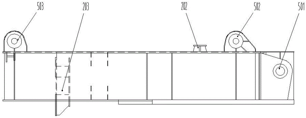
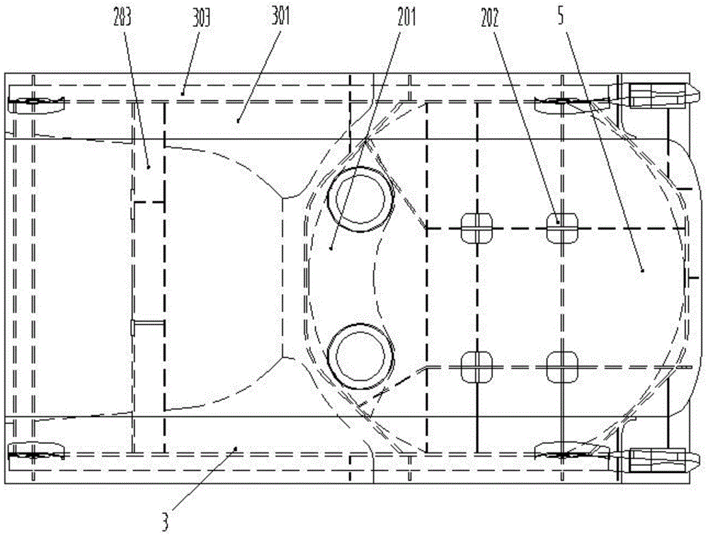
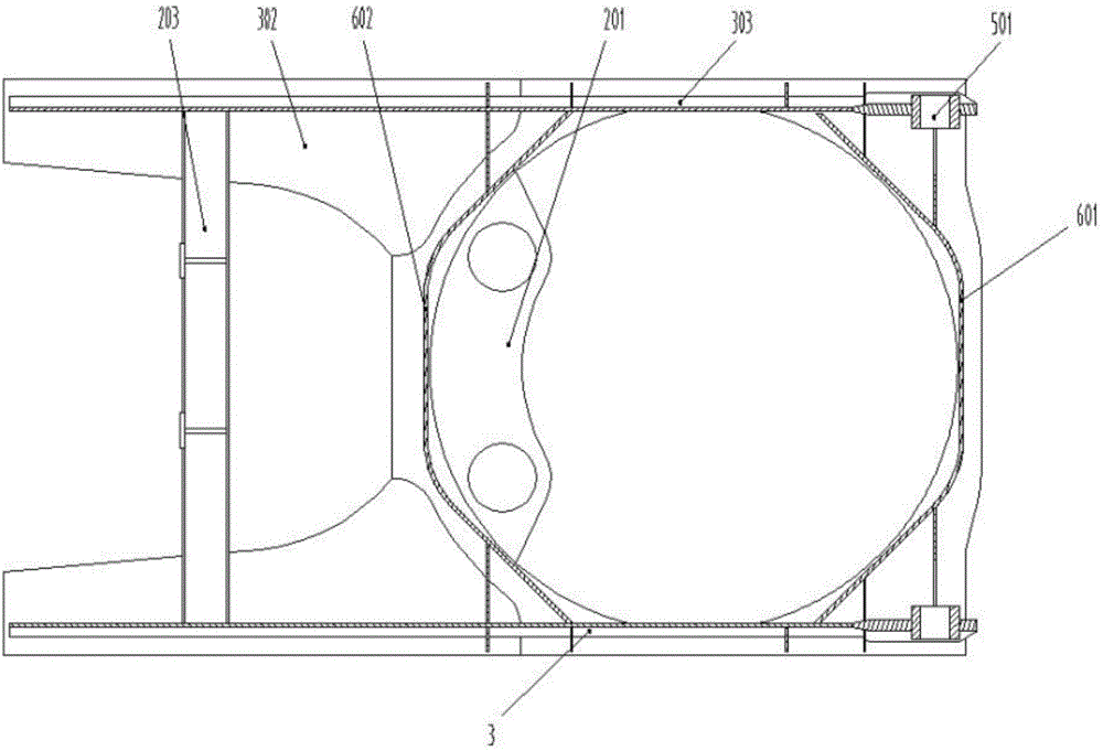
[0028] An embodiment of the present invention provides a turntable structure, such as Figure 1-3 As shown, the turntable structure includes a main body box 5 , and at least two I-beams 3 for fixing the A-frame 4 , a cylinder front plate 601 and a cylinder rear plate 602 are arranged inside the main body box 5 . to combine Figure 4 , the I-beam 3 includes an upper wing plate 301 and a lower wing plate 302 parallel to each other and a web 303 installed between the upper wing plate 301 and the lower wing plate 302, the upper wing plate 301 is connected with the main body box 5, and the web 303 The four legs 401 , 402 , 403 , 404 of the A-frame 4 are arranged in the main box 5 , that is to say, the web 303 and the upper wing 301 are arranged at an angle other than 90 degrees. Among them, the main body box 5 also includes a panel connected between the left and right upper wings 301 and a thick steel plate connected with the lower slewing bearing 7. The panel is relatively thin, ...

Embodiment 2

[0040] An embodiment of the present invention provides a crane, such as Figure 5 with Image 6 As shown, the crane includes the turntable structure 1 provided in the first embodiment, the A frame 4, the base column 8, the boom 11, the driver's cab 9, the machine room 10, the slewing mechanism and the luffing mechanism 13, the A frame 4, Base column 8 , boom 11 , driver's cab 9 , machine room 10 , slewing mechanism and luffing mechanism 13 are all arranged on the turntable structure 1 .

[0041] Wherein, the slewing mechanism includes: a slewing bearing 7 and a slewing reducer 14 , wherein the slewing reducer 14 is installed in the slewing reducer mounting support 201 . The second leg 402 and the third leg 403 of the A-frame 4 are located at the tail of the turntable structure 1, the first leg 401 and the fourth leg 404 of the A-frame 4 are located on the top surface of the head of the turntable structure 1, and the boom 11 The root is installed at the head of the turntable ...


PUM


Abstract

The invention discloses a rotary table structure and a crane having the rotary table structure, which belongs to the field of marine engineering equipment. The rotary table structure comprises a main body case; the interior of the main body case is provided with at least two I-shaped beams used for fixing an A-shaped rack, a barrel front plate and a barrel rear plate; each I-shaped beam comprises an upper wing plate, a lower wing plate and a web, wherein the upper wing plate and the lower wing plate are parallel, and the web is arranged between the upper wing plate and the lower wing plate; all the webs are arranged in the main body case along axis directions of four legs of the A-shaped rack, and two ends of the barrel front plate and two ends of the barrel rear plate are respectively fixed on the webs; the crane comprises the rotary table structure and the A-shaped rack. According to the invention, lightweight design of the rotary table structure is realized, the I-shaped beams replace a case-type beam and are used as main bearing and supporting structures for the rotary table structure, and since the weight of the I-shaped beams is smaller than the weight of the case-type beam, the weight of the rotary table structure is reduced; since the weight of the rotary table structure is reduced, the crane using the rotary table structure has reduced weight.

Description

technical field [0001] The invention relates to the field of ocean engineering equipment, in particular to a turntable structure and a crane with the turntable structure. Background technique [0002] Offshore cranes are usually installed on various offshore platforms and workboats for deep sea operations. Due to the limited load capacity and space of the platform or workboat where the offshore engineering crane is located, the requirements for the dead weight of the offshore engineering crane and the maximum turning radius at the stern of the turntable are usually quite strict. [0003] C-type offshore engineering crane refers to a wire rope luffing and truss-type jib crane with an A-frame structure. The C-type offshore engineering crane mainly includes a turntable structure, a hoisting mechanism, a luffing mechanism, a slewing mechanism and a base column. Among them, The hoisting mechanism, luffing mechanism and slewing mechanism are all arranged on the turntable structur...

Claims


Application Information

Patent Timeline
Patent Type & Authority Patents(China)
IPC IPC(8): B66C23/84
Inventor 杜鹏谭家翔霍小剑刘连进谭静轩邓祖学任攀
Owner WUHAN MARINE MACHINERY PLANT
Why Eureka
Try Eureka