Method for correcting absolute displacement of end point of vacuum laser collimation displacement measurement device

A technology of absolute displacement and displacement measurement, applied in measuring devices, optical devices, instruments, etc., can solve difficult problems and achieve the effect of saving engineering investment

Active Publication Date: 2014-01-08
CHINA WATER NORTHEASTERN INVESTIGATION DESIGN & RES
View PDF5 Cites 4 Cited by
  • Summary
  • Abstract
  • Description
  • Claims
  • Application Information

AI Technical Summary

Problems solved by technology

[0010] The invention provides a method for correcting the absolute displacement of the end point of a vacuum laser alignment displacement measurement device to solve the problem of difficulty in the layout and implementation of the current vacuum laser alignment displacement measurement system

Method used


Image

  • Method for correcting absolute displacement of end point of vacuum laser collimation displacement measurement device
  • Method for correcting absolute displacement of end point of vacuum laser collimation displacement measurement device

Examples


Embodiment Construction

[0034] Include the following steps:

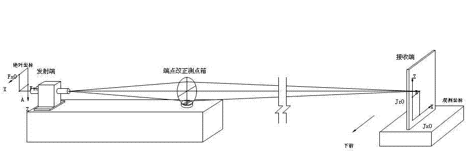
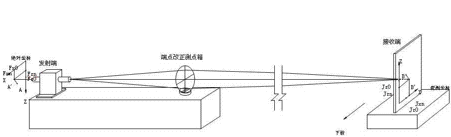
[0035] (1) Install either the transmitting end device or the receiving end device in a stable position. If the position is unstable, an absolute displacement measuring device for the end point must be installed;

[0036] (2) Install a measuring point box for displacement correction of the other end point within 5-20m from the end point. The measuring point box and the end point equipment are required to be installed on the same platform or ensure that the position of the calibration device is accompanied by the end point Simultaneous deformation;

[0037] (3) Calculate the relative displacement change between the receiving end and the transmitting end by measuring the displacement change of the position of the measuring point box, and calculate the relative displacement change between the receiving end and the transmitting end through the end point correction calculation method. The relative displacement change plus the absolute displa...


PUM


Abstract

The invention relates to a method for correcting the absolute displacement of an end point of a vacuum laser collimation displacement measurement device and belongs to the improvement on a building displacement monitoring method. Either transmitting terminal equipment or receiving terminal equipment is arranged in a stable position, a point measuring box for correcting the displacement of another end point is arranged in a range which is 5-20m from the end point, the relative displacement variation between a receiving terminal and a transmitting terminal is calculated by an end point correcting and calculating method through the measurement of the displacement variation of the position of the point measuring box, and the relative displacement variation is added to the absolute displacement of the end point to obtain the absolute displacement variation of the another end point. The method has the advantage that as only one measurement point is increased, measurement time hardly varies compared with other schemes, and the method not only can meet the layout requirement of a system but also can largely save engineering investment.

Description

technical field [0001] The invention belongs to the improvement of a building displacement monitoring method. Background technique [0002] The vacuum laser alignment displacement measurement device has been widely used in the displacement monitoring of linear buildings, which can measure the displacement changes in the horizontal X direction (perpendicular to the axis of the building) and the vertical Z direction. The system is mainly composed of laser emitting device, laser receiving device, measuring point box, vacuum pipeline, vacuum control system and data acquisition system. The principle and composition of the system are detailed in "Vacuum Laser Alignment Displacement Measuring Device" (DL / T 328-2010). [0003] The vacuum laser alignment displacement measurement device measures the relative displacement change of the measuring point relative to the transmitting end (where the laser emitting device is located) and the receiving end (where the laser receiving device i...

Claims


Application Information

Patent Timeline
Patent Type & Authority Applications(China)
IPC IPC(8): G01B11/02
Inventor 金正浩李俊富苏加林马军王德库王科峰徐岩彬李克绵孟中姜盛吉王珍萍朱奎卫彭立斌韩琳马玉华于柏强王洪洋薛立梅
Owner CHINA WATER NORTHEASTERN INVESTIGATION DESIGN & RES
Why Eureka
Try Eureka