

Over-current detection circuit and over-current protection circuit
An overcurrent protection circuit and overcurrent detection technology, applied in the field of circuits, can solve problems such as inability to capture system overcurrent signals in time, difficult motor protection, etc., to achieve rapid response, avoid potential safety hazards, and avoid failure to protect in time.
- Summary
- Abstract
- Description
- Claims
- Application Information
AI Technical Summary
Problems solved by technology
Method used
Image

Examples
Embodiment 1
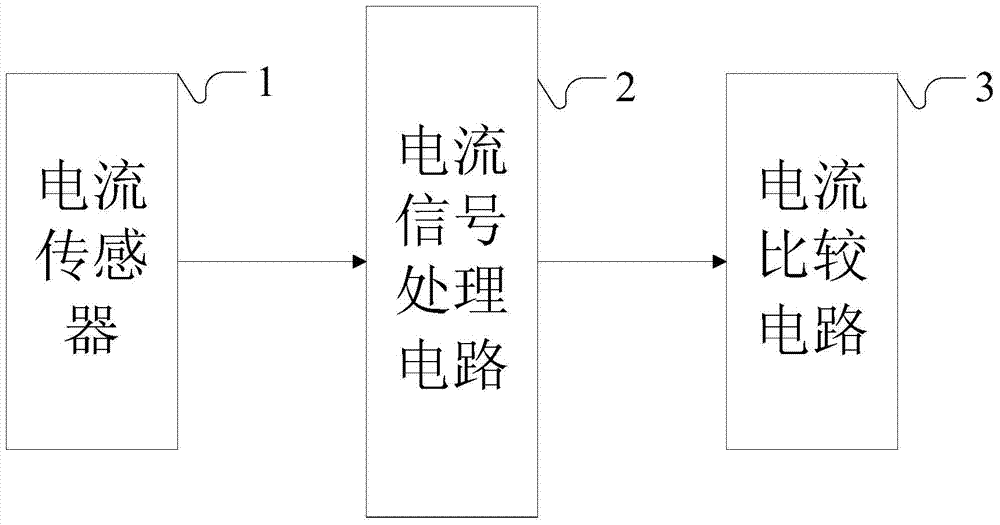
[0051] figure 1 It is a schematic diagram of an overcurrent detection circuit provided in the embodiment of the present application.
[0052] refer to figure 1 As shown, an overcurrent detection circuit provided in the embodiment of the present application includes:
[0053] The current sensor 1 is used to collect the current analog signal output by the motor power module;
[0054]In this embodiment of the application, the motor is usually a permanent magnet synchronous motor of an electric vehicle, and the AC current of the motor power module is collected by a Hall-type current sensor and converted into an analog voltage signal that can be input into an operational amplifier.
[0055] The current signal processing circuit 2 is connected with the current sensor 1, converts the current analog signal collected by the current sensor 1 into a measurable voltage signal of the operational amplifier, and performs filtering and isolation to output a voltage value;
[0056] In the e...
Embodiment 2
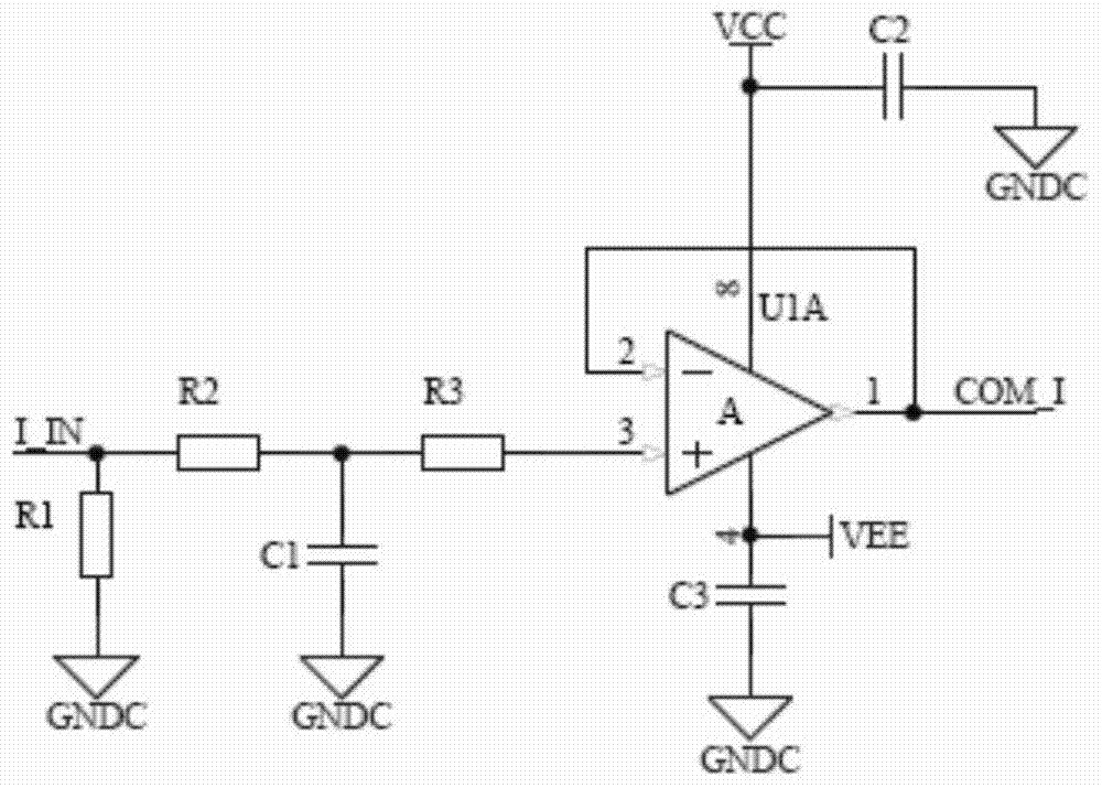
[0062] figure 2 It is a schematic diagram of a current signal processing circuit in an overcurrent detection circuit provided by an embodiment of the present application.
[0063] refer to figure 2 As shown, a current signal processing circuit in an overcurrent detection circuit provided in an embodiment of the present application includes:
[0064] The current input terminal I_IN is connected to the current sensor;
[0065] a first resistor R1, the first end of the first resistor R1 is connected to the current input terminal I_IN, and the second end of the first resistor R1 is grounded;
[0066] a second resistor R2, the first end of the second resistor R2 is connected to the current input terminal I_IN;
[0067] a first capacitor C1, the first end of the first capacitor C1 is connected to the second end of the second resistor R2, and the second end of the first capacitor C1 is grounded;
[0068] a third resistor R3, the first end of the third resistor R3 is connected t...
Embodiment 3
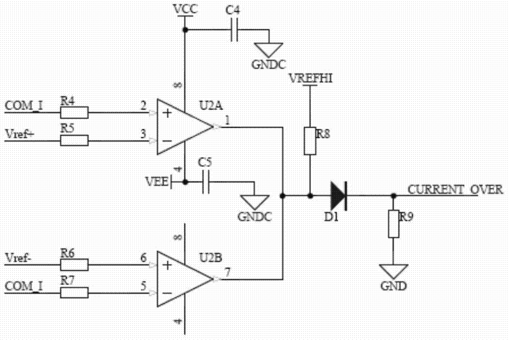
[0074] image 3 It is a schematic diagram of a current comparison circuit in an overcurrent detection circuit provided in an embodiment of the present application.
[0075] refer to image 3 As shown, a current comparison circuit in an overcurrent detection circuit provided in an embodiment of the present application includes:
[0076] The voltage input terminal COM_I is connected to the output terminal of the current signal processing circuit 2;
[0077] A fourth resistor R4, the first end of the fourth resistor R4 is connected to the voltage input terminal COM_I;
[0078] A fifth resistor R5, the first terminal of the fifth resistor R5 is used to input the reference voltage upper limit value Vref+;
[0079] A sixth resistor R6, the first terminal of the sixth resistor R6 is used to input the reference voltage lower limit value Vref-;
[0080] A seventh resistor R7, the first end of the seventh resistor R7 is connected to the voltage input terminal COM_I;
[0081] The fi...
PUM
 Abstract
Description
Claims
Application Information