
Determination Method of Rotating Blade-casing Friction Force

A determination method and technology of rotating blades, applied in special data processing applications, instruments, electrical digital data processing, etc., can solve problems such as blade bending, system influence, forced vibration, etc.

Active Publication Date: 2016-04-20
NORTHEASTERN UNIV LIAONING
View PDF2 Cites 0 Cited by
  • Summary
  • Abstract
  • Description
  • Claims
  • Application Information

AI Technical Summary

Problems solved by technology

Since the bending stiffness of the blade is much smaller than that of the casing, and because it rotates at a high speed during the working process, the blade will bend during collision and friction, resulting in forced vibration, which will affect the entire system

Method used


Image

  • Determination Method of Rotating Blade-casing Friction Force
  • Determination Method of Rotating Blade-casing Friction Force
  • Determination Method of Rotating Blade-casing Friction Force

Examples


Embodiment Construction

[0084] Below in conjunction with accompanying drawing and specific embodiment the present invention is described in further detail:

[0085] A method for determining frictional force of rotating blade-casing, comprising the steps of:

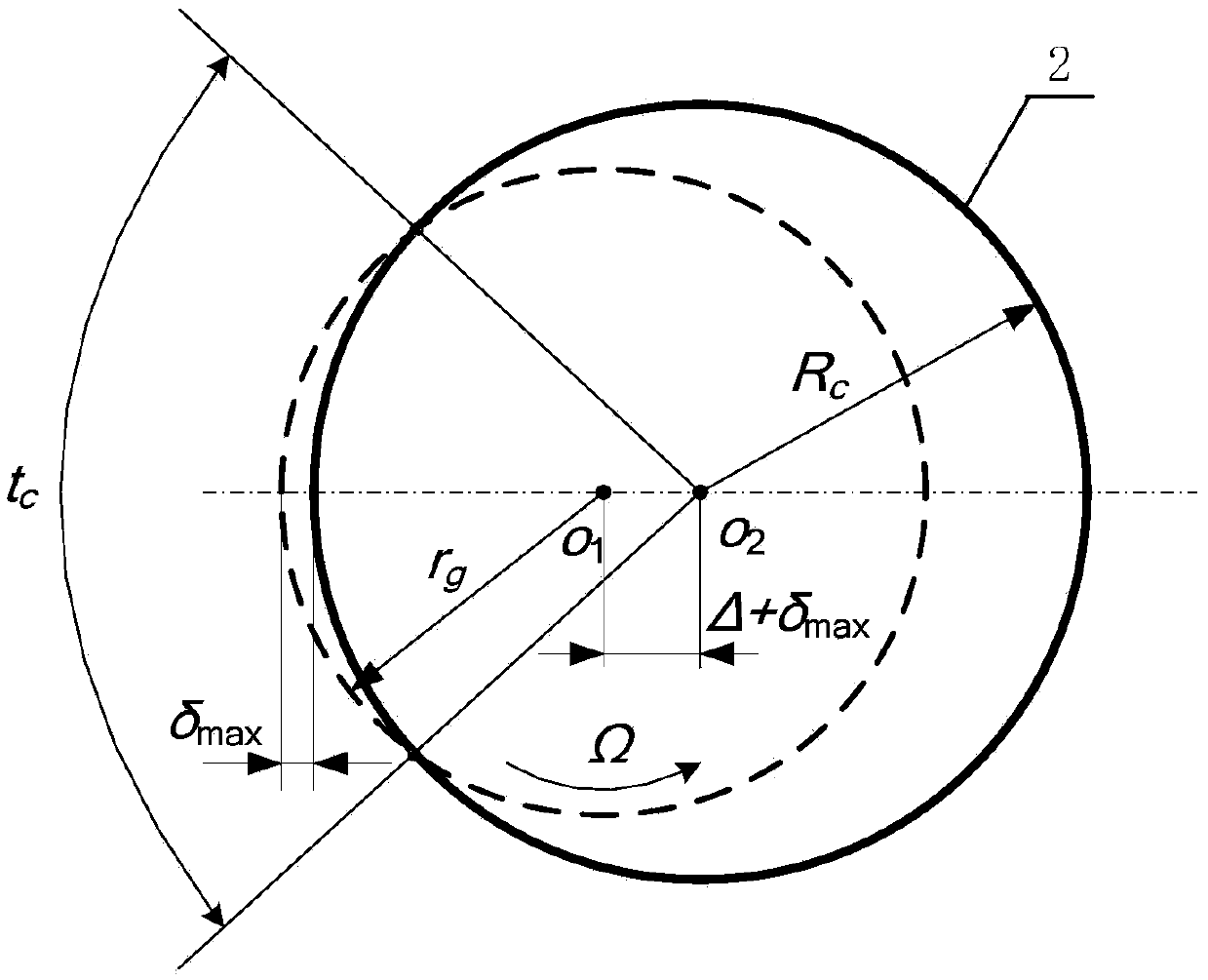
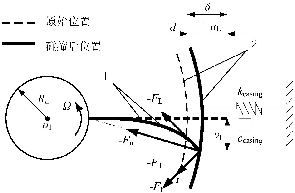
[0086] Step 1: Measure the geometric dimensions and operating conditions of the blade and casing, including the length L of the blade, the width b of the blade, the thickness h of the blade, and the radius R of the blade disc d , casing radius R c , the minimum distance c between the blade tip and the inner wall of the casing min and speed Ω;

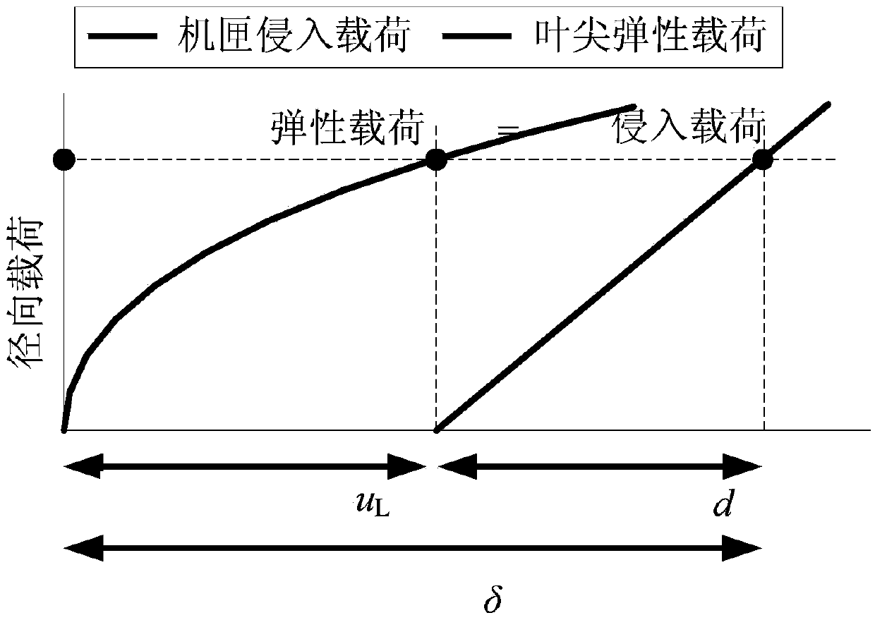
[0087] Step 2: According to the law of conservation of mechanical energy, the functional equation of the blade and casing at a certain moment is established:

[0088] Assume that the blade satisfies the conservation of mechanical energy during a certain time when the blade is in contact with the casing:

[0089] u e + U c =W(4)

[0090] in:

[0091] u e is the bending deformation energy of the bl...


PUM


Abstract

The method for determining the friction force between the rotating blade and the casing belongs to the field of mechanical dynamics technology. The invention includes the following steps: according to the law of conservation of mechanical energy, establishing the functional equation of the blade and the casing at a certain moment: Ue+Uc=W; establishing the force balance relationship between the blade and the casing to obtain the expression of the radial force Fn at the blade tip Formula:; According to the bending deformation of the blade, the tip radial force Fn is decomposed according to the normal and tangential directions of the blade tip: -FL=-Fncos[v′(L,t)], -FT=-Fnsin[v ′(L,t)]; Finally, the force at the blade tip is synthesized:, .

Description

technical field [0001] The invention belongs to the technical field of mechanical dynamics, and relates to a method for determining the frictional force of a rotating blade-casing, in particular to a rotating blade-casing which includes the rotation effect and bending effect of the blade itself and the rigidity of the casing How to determine friction force. Background technique [0002] At present, the existing methods for determining the blade-casing friction force mainly include the following: [0003] 1. The rubbing force model based on the conservation of collision energy [0004] Assuming that the blade is a cantilever beam, the relationship between the normal contact force and radial deformation of the blade is deduced, and the nonlinear dynamic characteristics of the system are analyzed in the case of single blade and multiple blades. The normal rubbing force of blade-casing during friction is: [0005] F n = ...

Claims


Application Information

Patent Timeline
Patent Type & Authority Patents(China)
IPC IPC(8): G06F19/00
Inventor 马辉太兴宇李朝峰闻邦椿
Owner NORTHEASTERN UNIV LIAONING
Learn More