Processing method of motor stator end plate

A processing method and motor stator technology, applied in the manufacture of stator/rotor body, etc., can solve the problems of low material utilization rate, inability to meet high-volume rapid production, low material utilization rate, etc., to improve profitability and competition level, and meet large Mass rapid production, the effect of improving material utilization

Inactive Publication Date: 2014-01-08
JIANGSU TONGDA POWER TECH
View PDF5 Cites 4 Cited by
  • Summary
  • Abstract
  • Description
  • Claims
  • Application Information

AI Technical Summary

Problems solved by technology

In this process, the remaining material produced when cutting the outer circle and the inner circle steel sheet produced by cutting the inner circle, due to their small size, cannot be reused in other products, have no use value, and will be discarded directly, resulting in a low utilization rate of materials , serious waste
At present, the material for making the low-voltage stator end plate generally adopts the steel plate material with a thickness of 2mm Q235-A. The material purchase cost is high, and the low material utilization rate will directly lead to the reduction of the profit and competition level of the enterprise.
In addition, when punching grooves in this manufacturing process, the stator grooves are punched with the central false hole and keyway positioning, which can only be punched out on a 16T single-type punching machine. This punching method is slow, and only 70-80 can be punched in one minute Slotted low-voltage stator end plates cannot meet the needs of mass and rapid production

Method used


Image

  • Processing method of motor stator end plate
  • Processing method of motor stator end plate
  • Processing method of motor stator end plate

Examples


Embodiment Construction

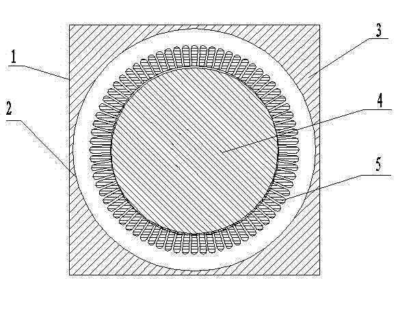
[0020] A kind of processing method of motor stator end plate of the present invention, such as figure 1 shown, including the following steps.

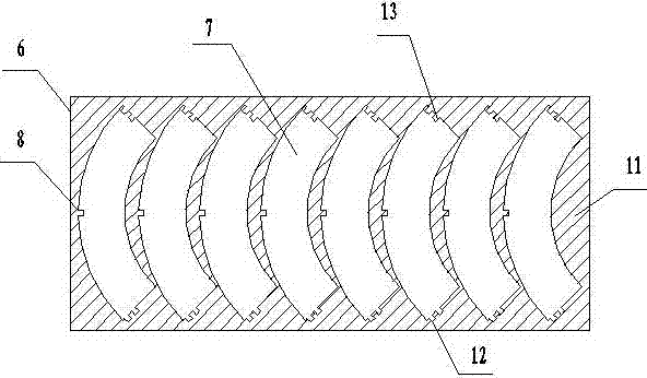
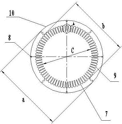
[0021] Step 1, cutting strip material 6: cut the steel plate into sections, and use a shearing machine to cut strip material 6. In this step, it is necessary to determine in advance the quantity of arc blocks 7 needed for splicing a finished motor stator end plate 10, and then calculate the length and width of the strip 6 according to the radius of the finished motor stator end plate 10 that needs to be spliced ​​(you can also combine several After the arc blocks 7 are arranged, it can be directly measured). The preferred implementation mode of this embodiment is: a finished motor stator end plate 10 plans to use four arc blocks 7 for splicing, and a motor needs to have two left and right finished motor stator end plates 10. For supporting use, the strip material 6 needs to be opened Out of 8 arc blocks 7.

[0022] Step 2, arc d...


PUM

PropertyMeasurementUnit
thicknessaaaaaaaaaa

Abstract

The invention discloses a processing method of a motor stator end plate. The processing method of the motor stator end plate comprises the steps of (1) cutting a bar stock; (2) using a dedicated die to carry out blanking on arc-shaped blocks with locating grooves; (3) carrying out circle splicing, carrying out two-sided burn-in on splicing connectors through welding rods, and carrying out polishing to achieve smoothness; (4) using an outer circle and the locating grooves to carry out locating, and punching groove profiles. When the processing method of the motor stator end plate is adopted, due to the facts that an original complete circle structure is replaced by an arc-shaped splicing structure, cutting of a square stock is changed into cutting of the bar stock, and an inner circle does not need to be cut, and waste of the area of an inner disk is avoided; due to the fact that the amount of waste produced through blanking of the arc-shaped blocks is much smaller than that of waste produced through cutting of the outer circle, waste of steel plate materials is reduced by about 70%, the use ratio of the materials is greatly improved, and the profit and the competition level of enterprises are greatly improved; in addition, due to the facts that the outer circle and the locating grooves are simultaneously used for locating and punching of the groove profiles, and the groove profiles can be directly punched through a high-speed notching press, the notching speed is high, operation can be carried out through only one person, the punching speed is increased to 300-400 times per minute from 70-80 times per minute of the traditional technology, production efficiency is high, and the requirement for mass rapid production can be met.

Description

technical field [0001] The invention relates to a motor processing method, in particular to a motor stator end plate processing method. The invention belongs to the field of motor stator iron core processing and manufacturing, and is suitable for processing end plates of Y, Y2, Y3, YB and other series of low-voltage conventional motors. Background technique [0002] At present, in the motor manufacturing industry, the production process of the low-voltage stator end plate is: first open the steel plate square material - punch the center false hole - cut the outer circle - cut the inner circle with the slotted belt. In this process, the remaining material produced when cutting the outer circle and the inner circle steel sheet produced by cutting the inner circle, due to their small size, cannot be reused in other products, have no use value, and will be discarded directly, resulting in a low utilization rate of materials , The waste is serious. At present, the material for ...

Claims


Application Information

Patent Timeline
Patent Type & Authority Applications(China)
IPC IPC(8): H02K15/02B23P15/00
Inventor 宋建强钱斌周燕红
Owner JIANGSU TONGDA POWER TECH
Why Eureka
Try Eureka