Striking prevention protection circuit for high-voltage direct current power supply circuit and realization method of striking prevention protection circuit

A power supply line, high-voltage direct current technology, applied in the direction of emergency protection circuit devices, electrical components, output power conversion devices, etc., can solve the problems of large inrush current in the DC input path, damage to power devices, etc., to improve work reliability, Effect of reducing inrush current and reducing input inrush current

Active Publication Date: 2014-01-08
SHENZHEN VMAX NEW ENERGY CO LTD
View PDF8 Cites 14 Cited by
  • Summary
  • Abstract
  • Description
  • Claims
  • Application Information

AI Technical Summary

Problems solved by technology

When the power distribution circuit breaker is frequently operated or the input DC power fails, the voltage of the bus capacitor will drop from the highest value to the DCDC undervoltage point. If the relay of the slow-start circuit fails to disengage in time, the input high-voltage DC will directly When switching into the module, due to the principle that the voltage of the bus capacitor cannot change suddenly, a short circuit will be formed in an instant, resulting in a large inrush current in the DC input path, which may damage the power devices in the path, such as the rectifier bridge and boost power device or insurance

Method used


Image

  • Striking prevention protection circuit for high-voltage direct current power supply circuit and realization method of striking prevention protection circuit
  • Striking prevention protection circuit for high-voltage direct current power supply circuit and realization method of striking prevention protection circuit
  • Striking prevention protection circuit for high-voltage direct current power supply circuit and realization method of striking prevention protection circuit

Examples


Embodiment Construction

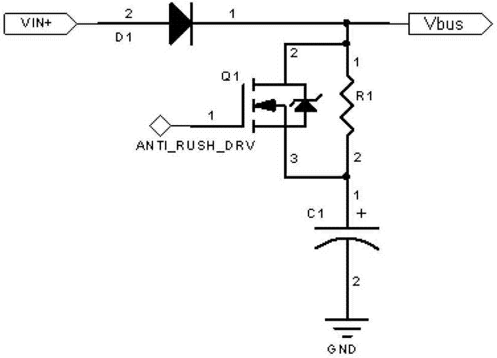
[0023] The invention discloses an anti-shock protection circuit for a high-voltage DC power supply line, which includes a positive busbar and a negative busbar, a busbar capacitor C1 connected between the positive and negative busbars, the busbar capacitor is connected in series with a first current-limiting resistor R1, and the first An electronic switch Q1 is connected in parallel at both ends of the current limiting resistor, and the positive busbar is connected with a control unit for detecting input voltage. When the control unit detects that the input voltage drops to the preset lower limit, the control electronic switch is turned off, and the first current-limiting resistor R1 acts to limit the inrush current when the high-voltage DC input is cut in; when the control unit detects that the input When the voltage reaches the preset upper limit, the electronic switch is controlled to be turned on to ensure that the loss during steady-state operation is as small as possible....


PUM


Abstract

The invention discloses a striking prevention protection circuit for a high-voltage direct current power supply circuit. The striking prevention protection circuit comprises a positive electrode bus, a negative electrode bus and a bus capacitor (C1), wherein the bus capacitor (C1) is connected between the positive electrode bus and the negative electrode bus, and is connected in series with a first current limiting resistor (R1), the two ends of the first current limiting resistor (R1) are connected in parallel with an electronic switch (Q1), the positive electrode bus is connected with a control unit for detecting the input voltage, and the control unit is also connected with the control end of the electronic switch and controls the on-off state of the electronic switch according to the input voltage. The invention also discloses a realization method of the striking prevention protection circuit. The first current limiting resistor is connected in series onto the bus capacitor for reducing the input striking current during the electrification, the two ends of the first current limiting resistor are connected in parallel with the electronic switch, the goals of energy saving and consumption reduction are reached through the short circuit of the first current limiting resistor in the stable-state work process, the electronic switch adopts the fast switch-off and slow switch-on control strategies, the striking current can be respectively and greatly reduced under any conditions, and the work reliability of a system is improved.

Description

technical field [0001] The invention relates to a protection circuit, in particular to an anti-shock protection circuit which performs buffer protection for a high-voltage direct current power supply line and has the advantages of energy saving and consumption reduction and a realization method thereof. Background technique [0002] In recent years, with the promotion of 3G and 4G services, the coverage of the communication network has been rapidly expanded, so higher requirements are put forward for the power supply system of the communication network. In the current communication power supply market, a new power supply mode HVDC (high voltage direct current power supply mode) is rapidly popularized and applied for IT and communication equipment. Compared with the traditional power supply mode UPS (uninterruptible power supply), HVDC has great advantages in terms of safety, energy saving and cost saving. At the same time, operators' recognition of the system is also increas...

Claims


Application Information

Patent Timeline
Patent Type & Authority Applications(China)
IPC IPC(8): H02M1/32H02H7/10
Inventor 刘钧张昌盛蒙杰成
Owner SHENZHEN VMAX NEW ENERGY CO LTD
Why Eureka
Try Eureka