IGBT (Insulated Gate Bipolar Transistor) driving circuit

A technology for driving circuits and freewheeling circuits, which is applied in electrical components, electronic switches, pulse technology, etc., can solve the problems of limited application range of IGBT series technology and short turn-on time of driving signals.

Inactive Publication Date: 2014-01-08
HARBIN INST OF TECH
View PDF3 Cites 0 Cited by
  • Summary
  • Abstract
  • Description
  • Claims
  • Application Information

AI Technical Summary

Problems solved by technology

Due to the certain characteristics of the volt-second product of the magnetic ring, when multiple IGBTs are connected in series, the overall volume of the circuit has to be considered. Therefore, when multiple IGBTs are connected in series, in order to reduce the overall power supply volume, the drive signal turn-on time is usually Very short (generally about 10 microseconds), which limits the application range of IGBT series technology

Method used


Image

  • IGBT (Insulated Gate Bipolar Transistor) driving circuit
  • IGBT (Insulated Gate Bipolar Transistor) driving circuit

Examples


specific Embodiment approach 1

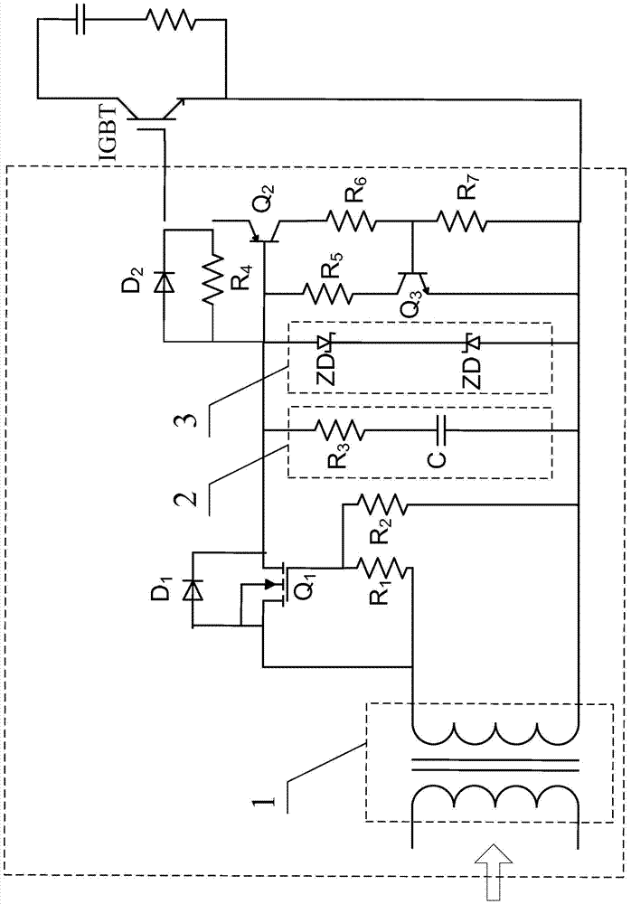
[0013] Specific implementation mode one: combine figure 1 Describe this embodiment mode, a kind of IGBT driving circuit described in this embodiment mode comprises ferrite bead 1, is characterized in that: it also comprises P-type MOSFET Q 1 , the first triode Q 2 , the second triode Q 3 , the first diode D 1 , the second diode D 2 , freewheeling circuit 2, voltage stabilizing circuit 3, first resistor R 1 , the second resistor R 2 , the fourth resistor R 4 , the fifth resistor R 5 , the sixth resistance R 6 and the seventh resistor R 7 , one terminal of the output end of the ferrite bead 1 is simultaneously connected to the first diode D 1 positive electrode, P-type MOSFET Q 1 source and the first resistor R 1 One end of the first resistor R 1 The other end is connected to the P-type MOSFET Q 1 gate, the first resistor R 1 with P-type MOSFET Q 1 The common terminal is connected to the second resistor R 2 One end of the freewheeling circuit 2 and the voltage st...

specific Embodiment approach 2

[0016] Specific implementation mode two: combination figure 1This embodiment is described. This embodiment is a further limitation of the IGBT drive circuit described in Embodiment 1. In this embodiment, the freewheeling circuit 2 is composed of a third resistor R 3 connected in series with capacitor C.

[0017] The energy storage and discharge functions of the freewheeling circuit 2 are realized by the capacitor C.

specific Embodiment approach 3

[0018] Specific implementation mode three: combination figure 1 Describe this embodiment. This embodiment is a further limitation on the IGBT drive circuit described in Embodiment 1. In this embodiment, the voltage stabilizing circuit 3 is composed of two Zener diodes in series, and the two Zener diodes connected to the positive pole.


PUM


Abstract

The invention provides an IGBT (Insulated Gate Bipolar Transistor) driving circuit, relates to the IGBT driving technology and aims at solving the problems that the pulse width of driving signals is narrow on the premise of meeting the consistency of the driving signals of the existing IGBT driving circuits connected in series. According to the IGBT driving circuit, the consistency of the driving signals can be guaranteed by utilizing the characteristic that the voltage-second product of a ferrite bead is a constant, when the positive pulse of the driving signals is over, a capacitor C provides the follow current for the IGBT driving signals, voltage is slowly declined, the pulse width of the driving signals is increased by 100 times, and the pulse width of the IGBT driving circuit gets rids of the limit on the voltage-second product of the ferrite bead. The IGBT driving circuit is used for driving a large-pulse-width power supply.

Description

technical field [0001] The invention relates to IGBT drive technology. Background technique [0002] With the continuous development of power electronics technology, the operating voltage of devices is also increasing. However, the IGBT (Insulated Gate Bipolar Transistor, Insulated Gate Bipolar Transistor) with high withstand voltage level is difficult to manufacture, and it is difficult for a single IGBT to meet the withstand voltage requirements of switching devices. Therefore, it is necessary to use IGBTs in series to meet the withstand voltage requirements. requirements. The switching action of the IGBT device is fast, and the IGBT circuit in series has strict requirements on the driving signal. It requires a reasonable voltage balance at the moment when the IGBT switch state changes and after it enters a stable working state, so as to prevent overvoltage on a certain device and damage the device; From the perspective of IGBT drive technology, it is required to elimina...

Claims


Application Information

Patent Timeline
IPC IPC(8): H03K17/567
Inventor 张可心张潮海周德胜
Owner HARBIN INST OF TECH
Why Eureka
Try Eureka