Pulse-jet dust removing device for bag-type dust collector

A technology of bag filter and pulse injection, which is applied to chemical instruments and methods, separation of dispersed particles, filtration of dispersed particles, etc., can solve the problems of high injection intensity, heavy maintenance workload, and high equipment cost, and achieve long-term filtration. Longer bag life, lower production cost, and adjustable blowing intensity

Active Publication Date: 2014-01-15
中钢集团天澄环保科技股份有限公司
View PDF5 Cites 0 Cited by
  • Summary
  • Abstract
  • Description
  • Claims
  • Application Information

AI Technical Summary

Problems solved by technology

[0003] It is not difficult to see that there are three problems in the above traditional dust removal device: First, each pulse valve can only clean one row of filter bags. When the number of filter bags is large, the consumption of pulse valves is large, the equipment cost is high, and the maintenance workload is heavy; The second is that the compressed air in the air bag is only released from one blowing pipe every time the dust is cleaned. The blowing air volume is often too large, and the blowing intensity cannot be controlled. After the dust is cleaned, the surface of the filter bag is too clean, and it is easy to cause PM2. 5 The fine particles penetrate and escape, which affects the collection efficiency of the dust collector for the fine particles; the third is that the blowing intensity is too high when cleaning the dust, which will shorten the service life of the filter bag

Method used


Image

  • Pulse-jet dust removing device for bag-type dust collector
  • Pulse-jet dust removing device for bag-type dust collector

Examples


Embodiment Construction

[0018] The bag type dust collector pulse jet dust cleaning device proposed by the present invention can be implemented in the following manner. Specific steps are as follows.

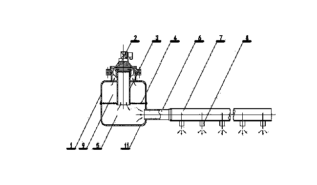
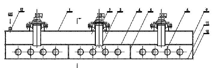
[0019] 1 Determine the volume of the air storage box (the cross-sectional size and length of the air storage box shell 1) according to the number of filter bags and the number of rows.

[0020] 2. The number of pulse valves 2 can be determined according to the nature of smoke and dust and the length of the gas tank shell 1.

[0021] 3. Drill a hole on the housing 1 of the air storage tank, and weld the base of the pulse valve 2 on it.

[0022] 4. Weld the gas storage tank shell 1 and the flat partition 4 to form the gas storage tank space.

[0023] 5. Weld the exhaust pipe 3 on the flat partition 4, and then install the pulse valve 2 on the base of the pulse valve 2.

[0024] 6. According to the number of filter bag rows, drill holes on the side of the gas distribution box shell 11, weld the vertical...


PUM


Abstract

The invention relates to a pulse-jet dust removing device for a bag-type dust collector, which comprises an air storage box shell 1 and air distribution box shells 11. Air storage box seal heads 9 are welded at both ends of the air storage box shell 1; air distribution box shell seal heads 10 are welded at both ends of the air distribution box shells 11; a horizontal separator 4 is arranged between the air storage box shell 1 and the air distribution box shells 11; vertical separators 5 are arranged in the air distribution box shells 11; an air storage box space is formed by the air storage box shell 1, the horizontal separator 4 and the air storage box seal heads 9; pulse valves 2 and exhaust pipes 3 of which the number is the same with that of the pulse valves 2 are arranged on the air storage box shell 1; one ends of the exhaust pipes 3 are connected with the pulse valves 2 and the other ends of the exhaust pipes 3 are welded on the horizontal separator 4; air distribution box spaces are formed by the horizontal separator 4, the vertical separators 5, the air distribution box shells 11 and the air distribution box shell seal heads 10; the exhaust pipes 3 are communicated with the air storage box space and the air distribution box spaces; a hole is formed on the air distribution box shell 11 in each formed air distribution box space to install an air distribution pipe 6; jetting pipes 7 are inserted in the air distribution pipes 6; spray nozzles 8 are configured on the jetting pipes 7; and an air inlet pipe 12 is arranged on the air storage box shell 1. The pulse-jet dust removing device for the bag-type dust collector overcomes the defects of a large number of the pulse valves, a large quantity of jetting air and unadjustable jetting intensity of a conventional pulse-jet dust removing device and has the characteristics of simple structure, compact arrangement, low manufacturing cost and adjustable jetting intensity.

Description

technical field [0001] The invention relates to a pulse-jet dust-cleaning device for a bag-type dust collector, in particular to a pulse-jet dust-cleaning device for bag-type dust collectors in the field of environmental protection. Background technique [0002] The pulse bag filter is a dust removal equipment that uses a filter bag made of filter material to filter the dusty gas and separate the dust from the gas. When the bag filter is running, more and more dust is accumulated on the surface of the filter bag, and the filtration resistance is also getting higher and higher. When the resistance reaches the set value, the bag filter should be cleaned. The traditional pulse cleaning method is realized by the pulse valve (which includes solenoid valve, diaphragm, valve body, valve seat, etc.), that is, the control system gives an electric signal, the solenoid valve of the pulse valve receives electricity, and the diaphragm Shift, open the exhaust pipe, the compressed gas sto...

Claims


Application Information

Patent Timeline
Patent Type & Authority Applications(China)
IPC IPC(8): B01D46/04B01D46/46
Inventor 姚群许汉渝张发有
Owner 中钢集团天澄环保科技股份有限公司
Why Eureka
Try Eureka