Flow photochemical reaction device

A photochemical reaction and flow technology, applied in feeding devices, chemical instruments and methods, chemical/physical processes, etc., can solve the problem of light source being difficult to replace.

Pending Publication Date: 2020-01-17
SHANGHAI INST OF ORGANIC CHEMISTRY - CHINESE ACAD OF SCI
View PDF2 Cites 1 Cited by
  • Summary
  • Abstract
  • Description
  • Claims
  • Application Information

AI Technical Summary

Problems solved by technology

[0007] Aiming at the defect that the photochemical reaction device in the prior art cannot carry out reactions involving gas, and the light source is not easy to replace, the purpose of the present invention is to provide a flow photochemical reaction

Method used


Image

  • Flow photochemical reaction device
  • Flow photochemical reaction device
  • Flow photochemical reaction device

Examples


Example Embodiment

[0098] Example 1

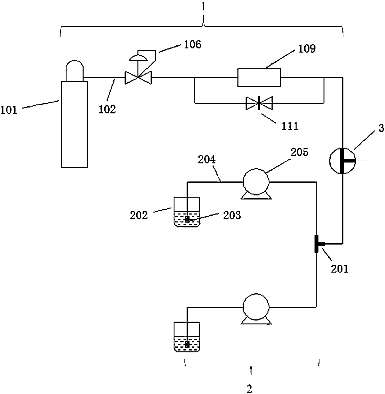
[0099] like Figure 1~2 As shown, the flow photochemical reaction device of this embodiment includes an air inlet system 1, a liquid inlet system 2, a micro-mixer 3, a light source 4, a constant temperature tank 5, a cold trap 6 and a micro flow tube 7 wound on the cold trap 6 ;

[0100] The inlet system 1 and the liquid inlet system 2 are connected to each other through the micro-mixer 3 and the micro-flow tube 7;

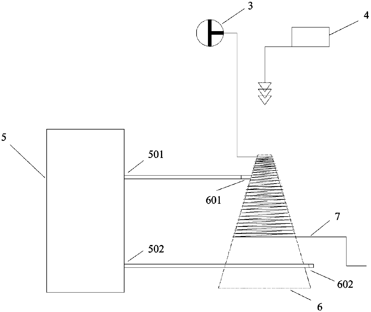
[0101] The cold trap 6 is a transparent glass closed container.

[0102] The cold trap 6 is set as a cone;

[0103] The light source 4 is located outside the cold trap 6 and arranged on the side of the vertex in the axial direction of the cold trap 6 . Setting the light source outside the cold trap is good for heat dissipation and uniform temperature.

[0104] The intake system 1 is a group, and the intake system 1 includes a gas cylinder 101, an air guide pipe 102, a pressure reducing valve 106, a gas mass flow meter 109 and a gas needle v...

Example Embodiment

[0124] Example 2

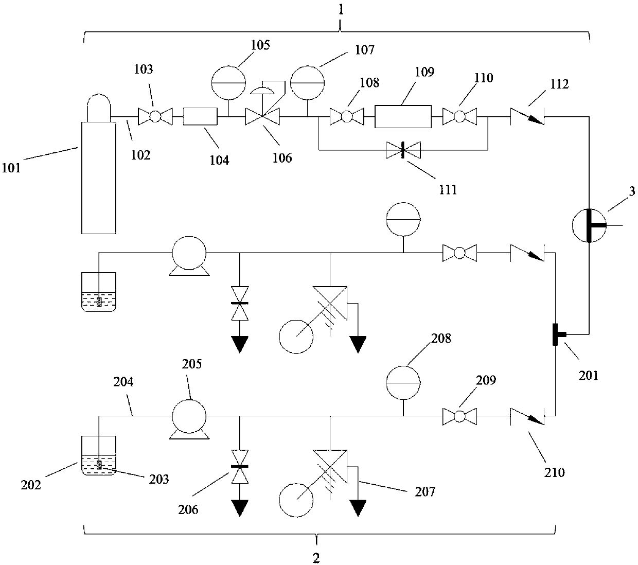
[0125] like Figure 3-4 As shown, on the basis of Embodiment 1, the flow photochemical reaction device of this embodiment also includes a back pressure regulator 8 and a product collector 9. A collector 9 is connected, and the product collector 9 collects the product flowing out from the back pressure regulator 8 . The back pressure regulator 8 is composed of a pressure gauge 801 and a pressure reducing valve 802 connected in sequence, wherein the pressure gauge 801 has a range of 0-1Mpa and a minimum resolution range of 0.05Mpa. The back pressure regulator 8 maintains a certain pressure for the reaction system, which is beneficial to the dissolution of the gas in the liquid phase so as to speed up the reaction process.

[0126] The air intake system 1 of the flow photochemical reaction device of this embodiment also includes a gas filter, a gas pressure gauge, a gas check valve, a gas ball valve and a pressure reducing valve.

[0127] The air duct 102 of...

Example Embodiment

[0139] Example 3

[0140] like Figure 5-6 As shown, the flow photochemical reaction device of this embodiment is based on the embodiment 2, and the cold trap 6 and the microfluidic tube 7 wound on the cold trap 6 are arranged in a protective box 10 . The direction of the cold trap 6 can be set as required, for example, the cone of the cold trap can stand vertically on the bottom of the box, or can be placed horizontally in the box.

[0141] The protective box 10 is made of stainless steel.

[0142] The protection box 10 is provided with a box door, and the box door is a sliding box door.

[0143] The protective box 10 is configured as a rectangular parallelepiped box.

[0144] The protective box 10 is provided with a temperature sensor 1001 , and the temperature probe of the temperature sensor 1001 extends into the protective box 10 and clings to the micro-flow tube 7 .

[0145] The protection box 10 is provided with a hole for the pipeline and the temperature probe of th...


PUM

PropertyMeasurementUnit
Inner diameteraaaaaaaaaa
The inside diameter ofaaaaaaaaaa
Outer diameteraaaaaaaaaa

Abstract

The invention discloses a flow photochemical reaction device. The device comprises a gas inlet system, a liquid inlet system, a micro mixer, a light source, a cold trap and a micro flow pipe wound around the cold trap, wherein the gas inlet system and the liquid inlet system are connected with the micro flow pipe through the micro mixer; the cold trap is arranged to be a cone; and the light sourceis located outside the cold trap and arranged at one side of the vertex of the cold trap in the axis direction. According to the flow photochemical reaction device, gas is allowed to be used as a rawmaterial to participate in a visible light reaction, design is safe, the light source is replaceable and high in illumination efficiency, and materials, temperature and pressure can be precisely controlled.

Description

technical field [0001] The invention provides a flow photochemical reaction device. Background technique [0002] The flow reactor is a classic research object in the field of chemical engineering. The small amount of reaction in the laboratory is directly transferred from the bottle (Batch) to the pipeline, which not only improves the reaction efficiency, shortens the reaction time, and does not have the effect of reactor amplification. , can run stably for a long time, narrowing the distance between the laboratory and the industrial production line, and is considered to be the development direction of synthetic chemistry in the future. Compared with the traditional photochemical reaction in the reaction bottle, the flow photoreactor has obvious advantages: the pipeline provides a larger surface area to volume ratio, which can improve the radiation efficiency, reduce the reaction time, and improve the conversion efficiency while reducing the catalyst load. and yield, so as...

Claims


Application Information

Patent Timeline
IPC IPC(8): B01J19/12B01J4/02
CPCB01J4/02B01J19/127B01J2204/002B01J2219/00051
Inventor 陈以昀李齐刘丹李德芳
Owner SHANGHAI INST OF ORGANIC CHEMISTRY - CHINESE ACAD OF SCI
Why Eureka
Try Eureka