Transmission mechanism of non-magnetic metal automatic separator

A technology of non-magnetic metal and automatic separator, which is applied in the field of non-magnetic metal removal device in the conveying system and the transmission mechanism of non-magnetic metal automatic separator, which can solve the problems of increasing workload, increasing the number of conveying materials, increasing production and operation costs, etc. , to achieve the effect of reducing production and operating costs, simplifying control circuits, and improving work efficiency

Active Publication Date: 2014-01-15
LONGI MAGNET CO LTD
View PDF7 Cites 2 Cited by
  • Summary
  • Abstract
  • Description
  • Claims
  • Application Information

AI Technical Summary

Problems solved by technology

In the process of completing a work, the motor needs to be braked and stopped after the material is received by the mechanical flap, and then reversed to start the motor to drive the mechanical flap to unload, which increases the starting and braking time of the motor once. If the mechanical flap continues to receive materials, the conveyed materials will also increase, which increases the workload of follow-up work. The other is that the electric push rod pushes the mechanical flap to turn over, and the speed of the electric push rod cannot be adjusted. The turning speed of the turning plate cannot be adjusted according to the different conveying materials
Then it is impossible to control the minimum amount of material brought out while picking out non-magnetic metal blocks, which increases the production and operation costs

Method used


Image

  • Transmission mechanism of non-magnetic metal automatic separator
  • Transmission mechanism of non-magnetic metal automatic separator
  • Transmission mechanism of non-magnetic metal automatic separator

Examples


Embodiment Construction

[0022] The following will clearly and completely describe the technical solutions in the embodiments of the present invention with reference to the accompanying drawings in the embodiments of the present invention. Obviously, the described embodiments are only part of the embodiments of the present invention, not all of them. Based on the embodiments of the present invention, all other embodiments obtained by persons of ordinary skill in the art without making creative efforts belong to the protection scope of the present invention.
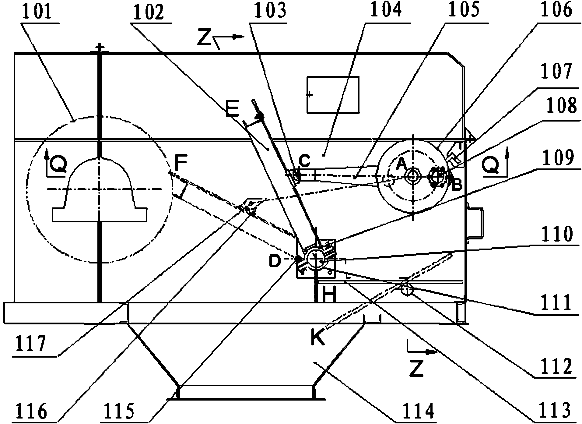
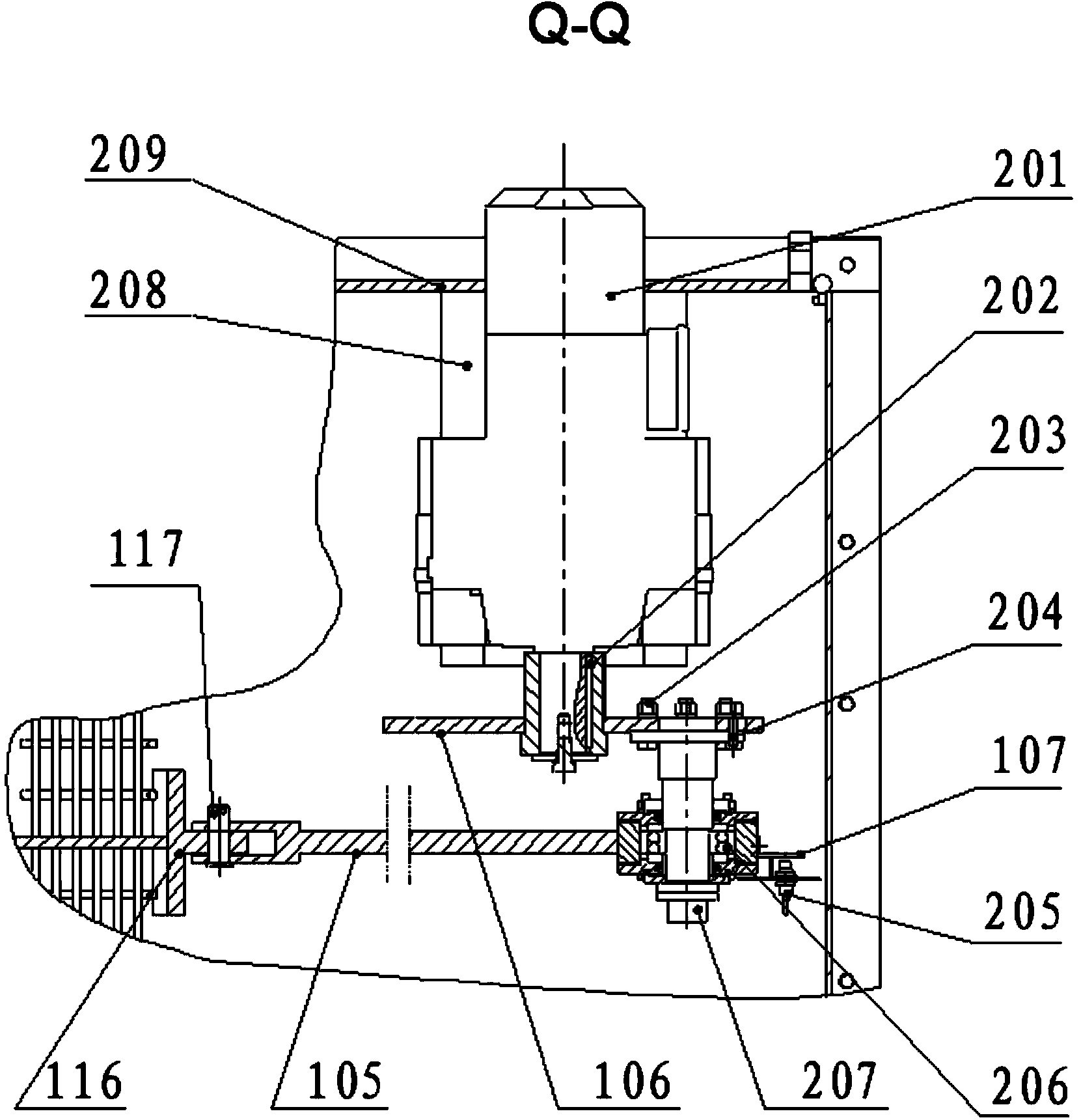
[0023] The core idea of ​​the technical solution adopted by the present invention is as follows: the mechanical flap is set as a rocker, and the turntable is set as a crank. The other end is connected with the mechanical flap. The turning plate shaft in the mechanical turning plate, the turntable is fixed on the box wall by the reduction motor, and the box wall is set as a frame, which constitutes a crank rocker mechanism. The deceleration motor...


PUM


Abstract

The invention discloses a transmission mechanism of a non-magnetic metal automatic separator. The transmission mechanism of the non-magnetic metal automatic separator comprises a transmission mechanism of a non-magnetic metal removing device, wherein in the transmission mechanism of the non-magnetic metal removing device, a crank-rocker mechanism consisting of a mechanical turnover plate (102), a connecting rod (105), a turnplate (106), an eccentric shaft (207) and a tank wall (209), and a material receiving plate (113), a material receiving shaft (112), a pull rod (302) and a locking ring (301) can put a small quantity of brought out materials back to a chute. According to the technical scheme, the rotation speed of a speed reducing motor is adjustable, can be properly adjusted according to the on-site working condition, so that the quantity of the materials brought out at the same time can be reduced, the work efficiency is improved, and the production and operation costs are reduced; the transmission mechanism of the non-magnetic metal automatic separator is simple in structure, reasonable in design and ingenious in concept, fills a gap of a conventional transmission mechanism of the non-magnetic metal automatic separator, and is worth of wide popularization and application.

Description

technical field [0001] The invention belongs to the field of non-magnetic material separation, in particular to a transmission mechanism of a non-magnetic metal automatic separator, which is a device for removing non-magnetic metals in a material conveying system. Background technique [0002] Non-magnetic metal automatic separator is a kind of high-efficiency and energy-saving picking equipment that can automatically pick out non-magnetic metal objects during material transportation. When the non-magnetic metal blocks mixed in the material pass through the metal detector, the detector can send out sound and light alarm signals in time, and send instructions to the special mechanical flap to separate the non-magnetic metal blocks. [0003] The shovel teeth and drill bits of the excavator are mixed in the process of mining and transportation. These shovel teeth and drill bits are alloy steel containing high manganese, which is very hard and can easily cause damage to the conv...

Claims


Application Information

Patent Timeline
Patent Type & Authority Applications(China)
IPC IPC(8): B07C5/36
Inventor 张承臣王博力吴文奎邵贵成
Owner LONGI MAGNET CO LTD
Why Eureka
Try Eureka