
Method for machining optical lens with three radii

A technology of optical lenses and processing methods, which is applied in optical surface grinders, metal processing equipment, manufacturing tools, etc., can solve the problems of inability to realize batch processing of multiple radius parts, inability to realize processing, etc.

Active Publication Date: 2014-01-15
NANYANG LIDA PHOTOELECTRIC
View PDF8 Cites 6 Cited by
  • Summary
  • Abstract
  • Description
  • Claims
  • Application Information

AI Technical Summary

Problems solved by technology

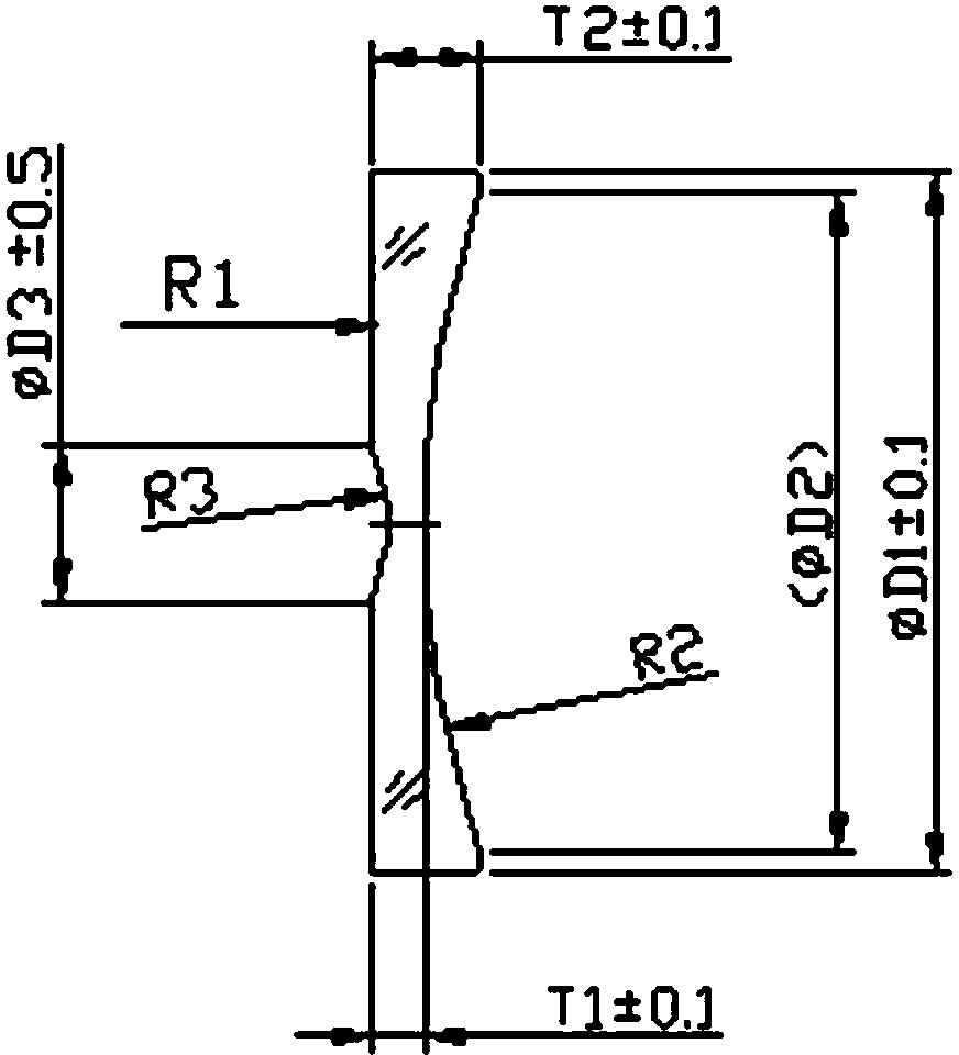
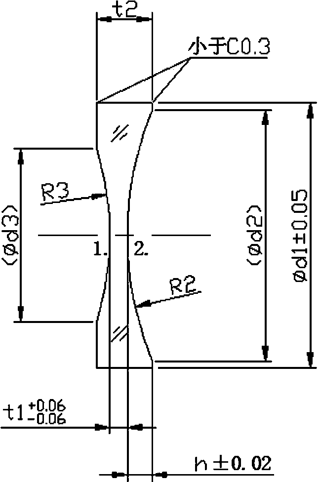
3 radii parts are a typical representative of them. 3 radii means that a total of 3 spherical surfaces need to be processed. The characteristic of this processing type is that one of the spherical surfaces has a diameter of only ¢10mm (D3), while the lens caliber is above ¢40mm (D1), which is normal. Unable to achieve processing, which has no precedent in lens processing before
[0004] In addition, one surface is added, but the relevant dimensions are increased by 3 or 4. How to use traditional equipment and testing equipment, how to control the vector height and total height in the grinding (fine grinding, polishing) process, how to formulate the process flow, and make the process simple and suitable for On-site control, suitable for batch processing, is the key to this technical field, because traditional technology methods cannot realize batch processing of parts with multiple radii

Method used


Image

  • Method for machining optical lens with three radii
  • Method for machining optical lens with three radii

Examples


Embodiment Construction

[0014] Such as figure 1 , 2 The finished drawing of optical lens products with 3 radii shown, and its specific processing flow:

[0015] Milling - fine grinding - edging - polishing - milling - fine grinding - polishing - coating; the 3 radius optical lens products are processed twice according to the above processing technology,

[0016] Among them, the first processing: realize the grinding processing of R2 and R3 surfaces, and at the same time, the center thickness and arc height meet the control requirements. Due to the very small diameter of the R3 surface (see figure 1 , 2 ), in order to realize the processing of this radius, the thickness of the blank should be increased by more than 0.7mm, and the diameter can reach a relatively large value during milling and grinding, generally 22~28mm, which can not only process this diameter, but also ensure the milling of the R1 surface during the secondary process Grinding, fine grinding allowance.

[0017] The secondary proc...


PUM


Abstract

The invention discloses a method for machining an optical lens with three radii. The optical lens is machined through two machining steps according to the technology, and the specific technology includes the steps of milling, accurate grinding, edging, polishing, milling, accurate grinding, polishing and film coating. The first machining step includes the steps of reserving a central thickness tolerance and a rise tolerance which are required to be controlled in the first machining step, and enabling the opening diameter of an R3 face to be increased in the first machining step so as to be suitable for polishing and machining, and meanwhile reserving an arc height allowance which is larger than 0.7mm when secondary milling is carried out on an R1 face. The second machining step includes the technological steps of mainly achieving grinding on the R1 face, enabling the total height to be guaranteed, meanwhile, controlling the opening diameter of an R2 face to be within a required range, conducting accurate grinding and polishing, and then enabling the total height to meet drawing requirements of parts. The whole technological processes are easy and convenient to carry out, and the method is suitable for field control, machining requirements are met, and the optical lens is suitable for mass machining.

Description

technical field [0001] The invention belongs to the field of manufacturing technology of optical parts, and in particular relates to a grinding process method of optical parts with three radii. Background technique [0002] The traditional lens has two working surfaces, and the traditional process uses three steps of milling, fine grinding and polishing. Through milling and fine grinding, the parts are controlled to meet certain roughness, surface shape (radius of curvature) and central thickness requirements, and the polishing process is used to control the parts to meet the requirements of surface shape (radius of curvature), appearance and other requirements of optical parts. The existing processing technology can only realize the processing and grinding of the left and right spherical surfaces of the lens. [0003] However, with the development of optical technology, multiple spherical lenses have appeared in order to meet the special optical path and structural require...

Claims


Application Information

Patent Timeline
IPC IPC(8): B24B13/00
CPCB24B1/00
Inventor 沙雪莹王磊王国新李智超
Owner NANYANG LIDA PHOTOELECTRIC
Learn More