Indirect printing press with movable inserted roller assembly and roller assembly thereof

A kind of printing machine, indirect technology, applied in the direction of printing machine, rotary printing machine, printing, etc., can solve the problems of high pressure, excessive compensation, deflection, etc.

Inactive Publication Date: 2016-02-24
XEROX CORP
View PDF5 Cites 0 Cited by
  • Summary
  • Abstract
  • Description
  • Claims
  • Application Information

AI Technical Summary

Problems solved by technology

This condition may be due to the crown being too tall and over compensating for the deflection, and the resulting higher pressure in the center of the nip

Method used


Image

  • Indirect printing press with movable inserted roller assembly and roller assembly thereof
  • Indirect printing press with movable inserted roller assembly and roller assembly thereof
  • Indirect printing press with movable inserted roller assembly and roller assembly thereof

Examples


Embodiment Construction

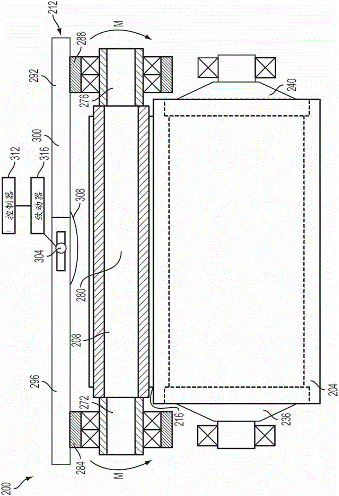
[0023] figure 1The illustrated image transfer system 200 includes an image receiving member 204 , a transfix roller 208 , and a support assembly 212 that accommodates deflection at the center of the transfix roller 208 and pressure variations along a nip 216 . The transfix roller 208 is configured to move into and out of engagement with the image receiving member 204 in a known manner. The transfix roller 208 is configured to apply pressure to the image receiving member 204 and form a nip 216 to transfer an ink image from the image receiving member 204 to the media passing through the nip 216 . The support assembly 212 is configured to apply different amounts of pressure to the central region and the end portions of the transfix roller 208 . The pressure applied by support assembly 212 to transfix roller 208 at nip 216 is transmitted through transfix roller 208 to image receiving member 204 .

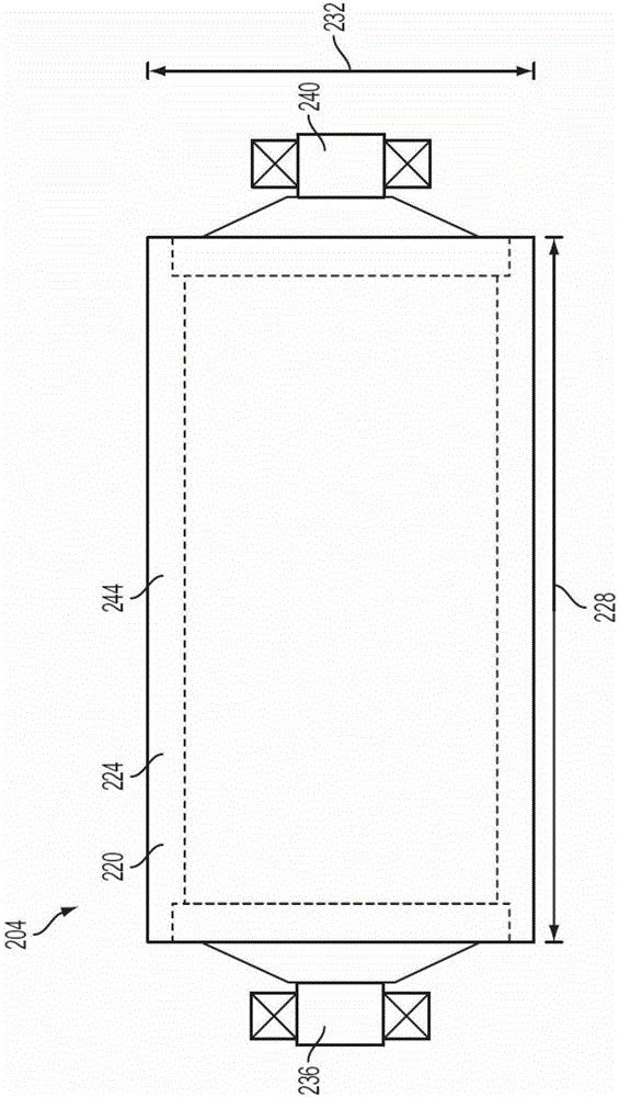
[0024] figure 2 Detailed features of the image receiving member 204 are depict...


PUM


Abstract

The present invention discloses an indirect printing press having a movable interposed roller assembly that enables the pressure in the transfer nip to be adjusted more precisely. The roll assembly includes: a thin-walled roll having a first end and a second end; a first pivotable collar supporting the first end of the roll and configured to apply a first moment to the roll. the first end of the roller; a second pivotable collar supporting the second end of the roller and configured to apply a second moment to the second end of the roller; and causing actuator. The actuator is operably connected to the first collar and the second collar and is configured to pivot the first collar and the second collar to apply the first moment and the second moment to the first end and the second end of the roller.

Description

technical field [0001] The systems described below relate to printing presses in which an ink image is transferred from the surface of an image receiving assembly to a recording medium, and, more particularly, to printing presses in which the image is transferred as the medium passes through a nip formed between a fuser roller and an image receiving member. A printing press that prints to recording media. Background technique [0002] A schematic diagram of a typical indirect printing machine is shown in Figure 8 , the printer includes a printhead that ejects phase change ink onto an image receiving member to form an image on the member. A solid ink imaging device, hereinafter simply referred to as a printer 110, has an ink loader 112 that receives and carries solid ink sticks. The ink sticks advance through the feed channel of the loader 112 until they reach the ink melting unit 114 . The ink melting unit 114 heats the portion of the ink stick that hits the ink melting u...

Claims


Application Information

Patent Timeline
Patent Type & Authority Patents(China)
IPC IPC(8): B41J2/01B41F13/008B41F13/34
CPCB41J2/0057B41F13/193B41F13/18
Inventor 布鲁斯·E·赛耶巴尔卡德·S·拉梅什雷切尔·L·麦格拉斯张斌克里斯托弗·A·迪鲁比奥
Owner XEROX CORP
Why Eureka
Try Eureka