Lifting-following rotary-type self-balancing tower crane

A self-balancing tower and rotating technology, applied in the direction of load hanging components, cranes, transportation and packaging, etc., can solve problems such as prone to overturning, difficult to remedy, hidden dangers, etc., to increase load capacity, reduce personnel, and reduce construction costs cost effect

Active Publication Date: 2014-01-15
重庆亚颖机电科技有限公司
View PDF7 Cites 3 Cited by
  • Summary
  • Abstract
  • Description
  • Claims
  • Application Information

AI Technical Summary

Problems solved by technology

This has brought hidden dangers to the construction to a certain extent, especially in self-elevating tower cranes, the height of the tower is often as high as tens of meters, and it is easy to overturn
In recent years, it can be seen from many tower crane overturning incidents in various places that illegal operation is one reason, but the existing tower design, once misoperation occurs, it is difficult to remedy

Method used


Image

  • Lifting-following rotary-type self-balancing tower crane
  • Lifting-following rotary-type self-balancing tower crane
  • Lifting-following rotary-type self-balancing tower crane

Examples


Embodiment 1

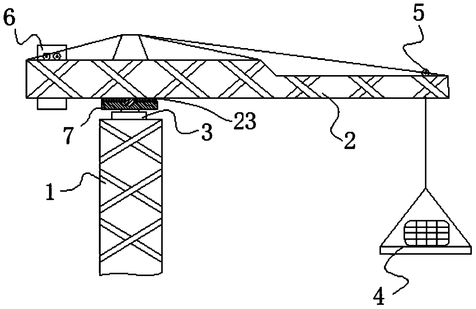
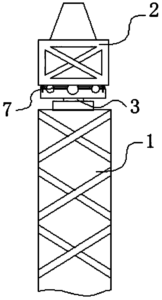
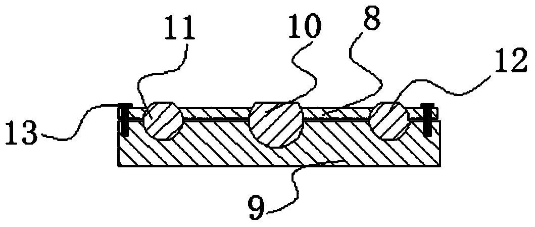
[0026] See the accompanying drawings: in the figure, a self-balancing rotary tower crane with lifting, including a tower 1, a luffing trolley 5, a counterweight 6 and a slewing mechanism 3, also includes a pitching cantilever 2, and a tower protection structure 7; The tower protection structure 7 includes a base plate 9 , a cover plate 8 and steel balls I10 ; the upper surface of the base plate 9 has a groove 15 , and the cover plate 8 has a through hole I18 .

[0027] In this embodiment, both the bottom plate 9 and the cover plate 8 are steel plates with a certain thickness, and the upper and lower ends thereof are horizontal surfaces. Described groove 15 promptly is the groove body that processes on the upper end surface of base plate 9, and upper opening, lower end are closed. The through hole I18 runs through the upper and lower end surfaces of the cover plate 8 .

[0028] The lower end of the steel ball I10 is placed in the groove 15, the cover plate 8 covers the upper e...

Embodiment 2

[0036] The basic structure of this embodiment is the same as that of Embodiment 1, except that improvements are made on the basis of Embodiment 1.

[0037] see Figure 5 or Image 6 , The two sides of the groove 15 on the bottom plate 9 are symmetrically provided with an arc-shaped groove I14 and an arc-shaped groove II16. The center of the arc groove I14 and the arc groove II16 is the center of the steel ball I10, that is, as Figure 5 As shown in , the shown groove 15 is a concave spherical groove, and its upper end surface is a circle, and the upper end surfaces of the shown arc-shaped groove I14 and arc-shaped groove II16 are both arcs, and the arc-shaped groove I14 and arc The upper end face of shape groove II16 is concentric with groove 15 upper end faces.

[0038] The two sides of the through hole I18 on the cover plate 8 are symmetrically provided with an arc-shaped through-hole I17 and an arc-shaped through-hole II19, and the lower end of the arc-shaped through-hole ...

Embodiment 3

[0046] The basic structure of this embodiment is the same as that of embodiment 1 or embodiment 2, but improvements are made on the basis of embodiment 1 or embodiment 2.

[0047] see figure 1 , the counterweight 6 is installed on the guide rail at the upper end of the pitch boom 2 through a pulley, and the position of the counterweight 6 on the pitch boom 2 is controlled by a hoist. That is, in the present embodiment, the structure of the counterweight 6 is the same as that of the luffing trolley, and can be changed like the luffing trolley. The design of this tower crane is called inclination (sensor) type self-balancing tower crane.

[0048] Self-balancing tower cranes have already appeared in the prior art with tension and pressure sensor technology for self-balancing. According to the principle of leverage, the moments of the balance arm and the boom are equal. However, in this solution, it is not ideal to control the amplitude of the counterweight 6 through the winch. ...


PUM


Abstract

The invention discloses a lifting-following rotary-type self-balancing tower crane and aims to provide a tower crane design capable of effectively protecting the tower frame body, improve the anti-overturning capacity of the tower crane, increase the counter weight and the bearing capability of the tower crane, and enable the tower crane to be suitable for transporting and hoisting large-scale materials and components of buildings, equipment and facilities. The lifting-following rotary-type self-balancing tower crane comprises a tower frame, a luffing trolley, a clump weight, a rotary mechanism, a luffing cantilever and a tower frame protection structure. The invention worthily illustrates that in a conventional tower crane structure, the cantilever is also called a big arm and is connected to the front and rear sides of a cone pillar at the upper end of a rotary mechanism, one side of the connection point of the cantilever is provided with a balance arm or a counter weight arm and the other side of the connection point is provided with a suspension arm. In the invention, the basic structure of the luffing cantilever is basically the same as the existing cantilever structure and only the connecting manner of the cantilever and the rotary mechanism is changed as shown below. Therefore, the cantilever of the lifting-following rotary-type self-balancing tower crane can luff, so that the cantilever is named the luffing cantilever to be distinguished from the cantilever in the prior art.

Description

technical field [0001] The invention relates to the field of construction equipment for construction projects, in particular to a tower crane. Background technique [0002] Tower crane, that is, tower crane, is the most commonly used lifting equipment on construction sites. It is used to lift construction materials such as steel bars, cement, and scaffolding used in construction. It is an indispensable equipment for building construction. Common tower cranes include tower frame, luffing trolley, counterweight, slewing mechanism, operating room and cantilever. [0003] In the existing trolley-luffing tower cranes, the function of the tower tip is to bear the upper load transmitted from the jib stay rope and the balance jib stay rope, and transmit it directly through the turntable through structural components such as the slewing tower, turntable, bearing, etc. Give the tower structure. The top of the self-elevating tower has a truncated cone column type, a forward or backw...

Claims


Application Information

Patent Timeline
Patent Type & Authority Applications(China)
IPC IPC(8): B66C23/88B66C23/72B66C23/62B66C13/40
Inventor 王智浩王亚
Owner 重庆亚颖机电科技有限公司
Why Eureka
Try Eureka