Novel container valve for fire trace tube fire-extinguishing device

A technology of fire extinguishing device and fire detection tube, which is applied in valve device, lift valve, fire rescue and other directions, can solve the problems of wrong opening of container valve, insufficient fire extinguishing time and lack of rationality, etc.

Active Publication Date: 2014-01-15
福建天广消防有限公司
View PDF8 Cites 12 Cited by
  • Summary
  • Abstract
  • Description
  • Claims
  • Application Information

AI Technical Summary

Problems solved by technology

However, in the actual use process, in order to maintain the normal working state of the fire detection tube, ensure the stability of the system and prevent the system from being opened by mistake, maintenance personnel need to check frequently
When the pressure at the fire detection tube drops, the pressure at the fire detection tube needs to be replenished manually, the maintenance cost is high, and the timeliness cannot be guaranteed. If the fire detection tube leaks for a long time, the container valve will be opened by mistake, wasting The fire extinguishing agent brings a lot of troubles to people, reducing the stability and reliability of the entire fire extinguishing device; because the spring is a vulnerable part, it is easy to be damaged by rust after long-term use, which reduces the performance of the entire fire extinguishing device , the service life is shortened; the whole structure is complex, not compact, lack of rationality, cumbersome processing and assembly, slow maneuvering response, not timely fire extinguishing, insufficient practicability, needs to be improved

Method used


Image

  • Novel container valve for fire trace tube fire-extinguishing device
  • Novel container valve for fire trace tube fire-extinguishing device
  • Novel container valve for fire trace tube fire-extinguishing device

Examples


Embodiment Construction

[0053] In order to further explain the technical solutions of the present invention, specific examples are given below to illustrate in detail.

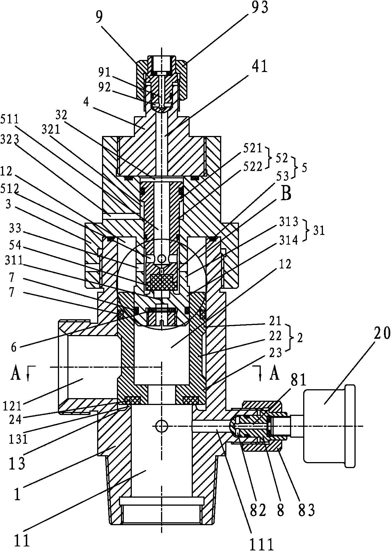
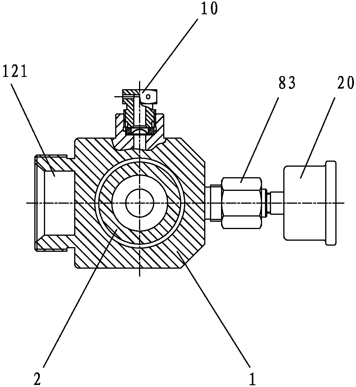
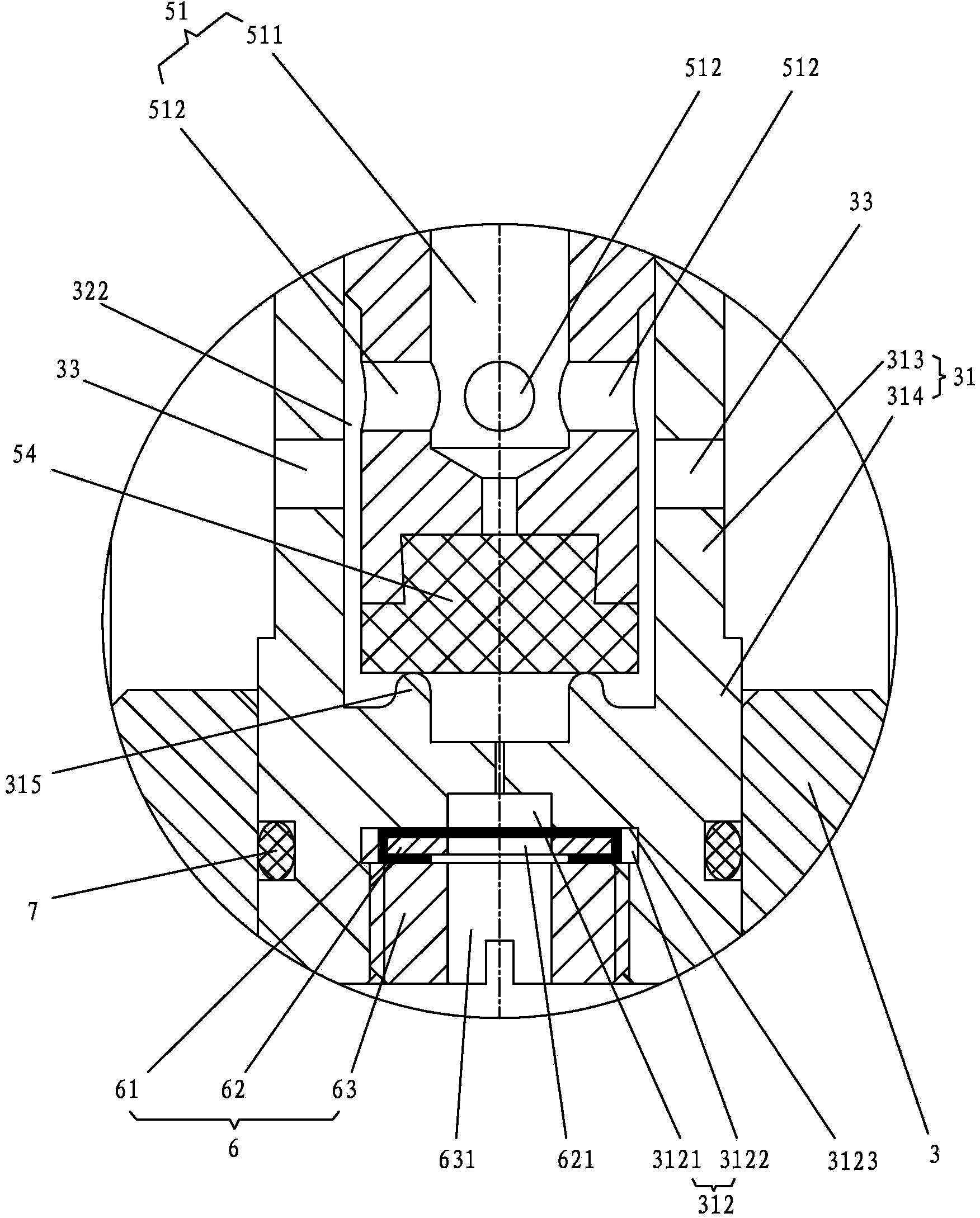
[0054] The novel container valve of a kind of fire detection tube fire extinguishing device of the present invention, as Figure 1-4 As shown, it includes a valve body 1, a valve disc 2, a valve cover 3 and a gland 4 communicating with a fire detection tube (not shown in the figure).

[0055] The valve body 1 has a lower chamber 11 that communicates with the fire extinguishing agent container (not shown in the figure) and has a lower inflation port 111, and an upper chamber 12 with a fire extinguishing agent nozzle 121; the valve cover 3 is connected to the valve in a sealed and firm manner. The upper end of the body 1; the gland 4 is connected to the upper end of the valve cover 3 in a sealed and firm manner; the valve cover 3 extends coaxially downwards with an extension 31 in the upper chamber 12, and the valve flap 2 is slidable ...


PUM


Abstract

The invention provides a novel container valve for a fire trace tube fire-extinguishing device. The novel container valve comprises a valve body, a valve clack, a valve cover and a gland. Therefore, a structural form of a container valve for a traditional fire-extinguishing device is changed; before use, pressure gas is filled in a fire trace tube end of the gland, and a fire extinguishing agent container is filled with a fire extinguishing agent through a lower inflation port; during use, if gas slowly leaks from the fire trace tube, nitrogen in a lower cavity jacks a pressure balance piston through pores, and gas is supplemented into the fire trace tube; when a fire occurs, the fire trace tube is broken and gas leaks, nitrogen in the fire trace tube and at the upper end of the valve clack rapidly leaks, pressure above the pressure balance piston and the valve clack is rapidly reduced, the leakage flow cannot be met by the flow of the pores, the valve clack is jacked by the nitrogen in the lower cavity, and the fire extinguishing agent is entrained to eject for extinguishing the fire through a fire extinguishing agent nozzle. Therefore, automatic gas supplementation of the fire trace tube can be timely and efficiently realized, and the maintenance cost is low. Moreover, the novel container valve is stable and reliable in performance, simple, novel, reasonable and compact in structure, fast in start, timely in fire extinction and high in practicability.

Description

technical field [0001] The invention relates to the field of a fire detection tube type fire extinguishing device, in particular to a novel container valve of a fire detection tube fire extinguishing device. Background technique [0002] The fire detection tube fire extinguishing device is known, as Chinese utility model patent CN201120045189.8 discloses a kind of fire detection tube automatic fire extinguishing device, which comprises a fire extinguishing agent storage bottle, a bottle head valve, a fire detection tube, and a protected area. Pipes are arranged in the protected area, and one end of the fire detection tube exposed to the protected area is equipped with a tee, two of which are respectively connected to the fire detection tubes at both ends, and the other is through the inlet pipeline Connect a pressure alarm, the pressure alarm includes a pressure gauge, a pressure switch, a sound alarm module, and a remote alarm signal interface module, the inlet pipeline of ...

Claims


Application Information

Patent Timeline
Patent Type & Authority Applications(China)
IPC IPC(8): F16K1/32F16K1/36A62C35/00
CPCA62C37/11
Inventor 吴献琴陈秀玉
Owner 福建天广消防有限公司
Why Eureka
Try Eureka