AI technical title is built by Patsnap AI team. It summarizes the technical point description of the patent document.
An optical imaging lens and lens technology, applied in optics, optical components, instruments, etc., can solve the problems of insufficient field of view, insufficient clarity, poor imaging quality, etc., and achieve simple lens structure, reduced lens volume, and easy matching. Effect
Active Publication Date: 2014-01-15
深圳市合力泰光电有限公司
View PDF6 Cites 6 Cited by
Summary
Abstract
Description
Claims
Application Information
AI Technical Summary
This helps you quickly interpret patents by identifying the three key elements:
Problems solved by technology
Method used
Benefits of technology
Problems solved by technology
However, there are two problems when the simplified optical lens is matched with commonly used imaging chips: first, the field of view is not large enough, the horizontal full field of view is only about 120-130°, and the diagonalfull field of view is only 140-150° °; Second, the image quality is poor and the definition is not enough
Method used
Image
Click on the blue label to locate the original text in one second.
Reading with bidirectional positioning of images and text.
Examples
Embodiment 1
[0062] This embodiment proposes relevant parameters of the optical imaging lens, specifically as follows:
[0063] Table 1 Mirror parameters
[0064]
[0065] Table 2 Aspheric Coefficient Parameters
[0066]
[0067] k, a 1 , a 2 , a 3 , a 4 , a 5 , a 6 , a 7 is the aspheric coefficient.
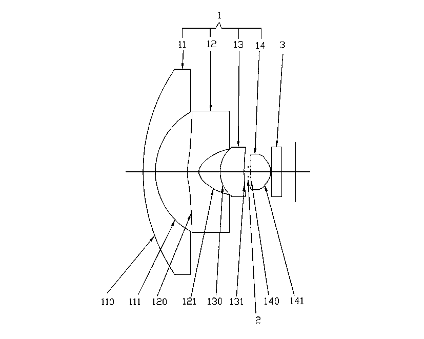
[0068] The thickness in Table 1 is the distance from this surface to the next surface. As shown in Table 1, the thickness of the first surface 110 is 0.93, which means that the thickness of the center of the first lens 11 is 0.93 mm; the thickness of the second surface 111 is 2.42 mm. , that is, the distance between the second surface 111 and the third surface 120 is 2.42 mm, and so on.
[0069] In this embodiment, F=0.83, f 1 = -11.27, f 2 = -1.89, f 3 =2.91,f 4 =1.82, L=11.54, L h =1.89. L / F>13, so the maximum chief ray angle is smaller, so it is easier to match with the imaging chip. L h / F>1.5, the rear focal length of the lens is larger, which is convenient for la...
Embodiment 2
[0077] Table 3 mirror parameters
[0078]
[0079] Table 4 Aspheric Coefficient Parameters
[0080]
[0081] k, a 1 , a 2 , a 3 , a 4 , a 5 , a 6 , a 7 is the aspheric coefficient.
[0082] Among the above parameters, F=0.83, f 1 =-11.33, f 2 =-1.89, f 3 =2.91,f 4 =1.80, L=11.53, L h =1.88. L / F>13, so the maximum chief ray angle is smaller, so it is easier to match with the imaging chip. L h / F>1.5, the back focus of the lens is larger, which is convenient for later focusing and assembly.
[0083] Such as Figure 11 As shown, the pixel height H 1 =1.788mm, H 2 =2.232mm, satisfying 1.788≤1.792≤2.232≤2.24, namely H 1 ≤0.8D≤H 2 ≤D. Therefore, the optical imaging lens provided by the present invention has a super large field of view with a full horizontal field of view not less than 180° and a diagonalfull field of view not less than 219°.
PUM
Abstract
The present invention provides an optical imaging lens which comprises a lens set. The lens set comprises the following components which are coaxial and are successively arranged from an object side to the image side: a first lens with a negative diopter, a second lens with a negative diopter, a third lens with a positive diopter, and a fourth lens with a positive diopter. Furthermore the lens set satisfies the following relationships: L / F>13, -15<f1 / F<-12, Lh / F>1.5; wherein the focal length of the first lens is set to f1, the focal length of the lens set is set to F, the optical total length of the optical imaging lens is set to L, and an optical back focal length is set to Lh. The optical imaging lens provided by the invention can be matched with an imaging chip more easily, and has an super-large view field which has a horizontal-direction full view field that is not smaller than 180 DEG and a diagonalfull view field that is not smaller than 219 DEG. The optical imaging lens has the following advantages: small number of adopted lens, simple lens structure, effective lens volume reduction and high imaging quality.
Description
technical field [0001] The invention relates to an optical device, in particular to a super wide-angle optical imaging lens. Background technique [0002] In surveillance and vehicle camera equipment, optical imaging lenses are extremely important components. The field of view and image quality of the optical lens directly determine the shooting range and imaging clarity of the imaging device, so there are high requirements for the equipped optical lens. Due to the complex structure and high cost of the equipped optical lens, it is not conducive to the promotion of monitoring and vehicle-mounted camera equipment. In order to facilitate the popularization and use of imaging equipment, reducing its cost has become an inevitable trend, so many manufacturers have adopted the method of simplifying the number of lenses of optical lenses to achieve this goal. However, there are two problems when the simplified optical lens is matched with commonly used imaging chips: first, the f...
Claims
Application Information
Patent Timeline
Application Date:The date an application was filed.
Publication Date:The date a patent or application was officially published.
First Publication Date:The earliest publication date of a patent with the same application number.
Issue Date:Publication date of the patent grant document.
PCT Entry Date:The Entry date of PCT National Phase.
Estimated Expiry Date:The statutory expiry date of a patent right according to the Patent Law, and it is the longest term of protection that the patent right can achieve without the termination of the patent right due to other reasons(Term extension factor has been taken into account ).
Invalid Date:Actual expiry date is based on effective date or publication date of legal transaction data of invalid patent.

