Groove step surface self-returning type electromagnet

A stepped surface and electromagnet technology, applied in the field of electromagnets, can solve the problems of the natural frequency of the electromagnet affecting the return time of the armature, the difficulty of maintenance, and the complicated internal structure, etc., and achieve simple structure, low manufacturing cost, and good restoring force characteristics Effect

Inactive Publication Date: 2014-01-15
ZHEJIANG UNIVERSITY OF SCIENCE AND TECHNOLOGY
View PDF5 Cites 4 Cited by
  • Summary
  • Abstract
  • Description
  • Claims
  • Application Information

AI Technical Summary

Problems solved by technology

However, because it only relies on a return spring when it is reset, the stiffness of the return spring affects the return time of the armature and the natural frequency of the electromagnet.
Moreover, as a mechanical part, the spring will inevitably experience fatigue, fracture or corrosion during use, which will affect the service life of the electromagnet; the installation of the spring also makes the internal structure complicated, and the more complex structure will , relatively easy to damage, and the difficulty of maintenance is relatively large

Method used


Image

  • Groove step surface self-returning type electromagnet
  • Groove step surface self-returning type electromagnet
  • Groove step surface self-returning type electromagnet

Examples


Embodiment 1

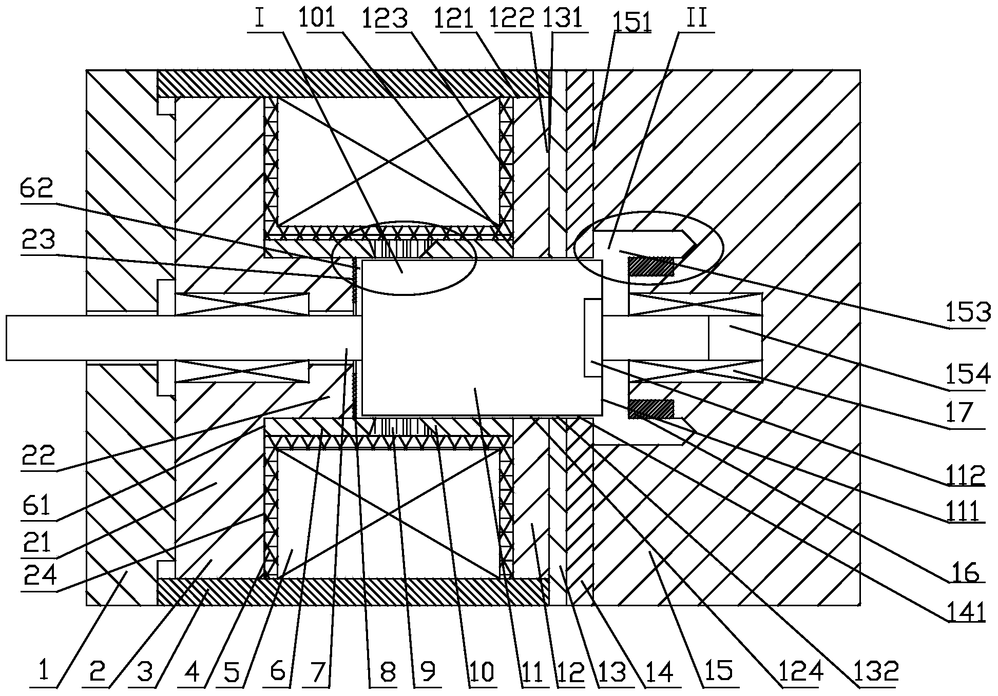
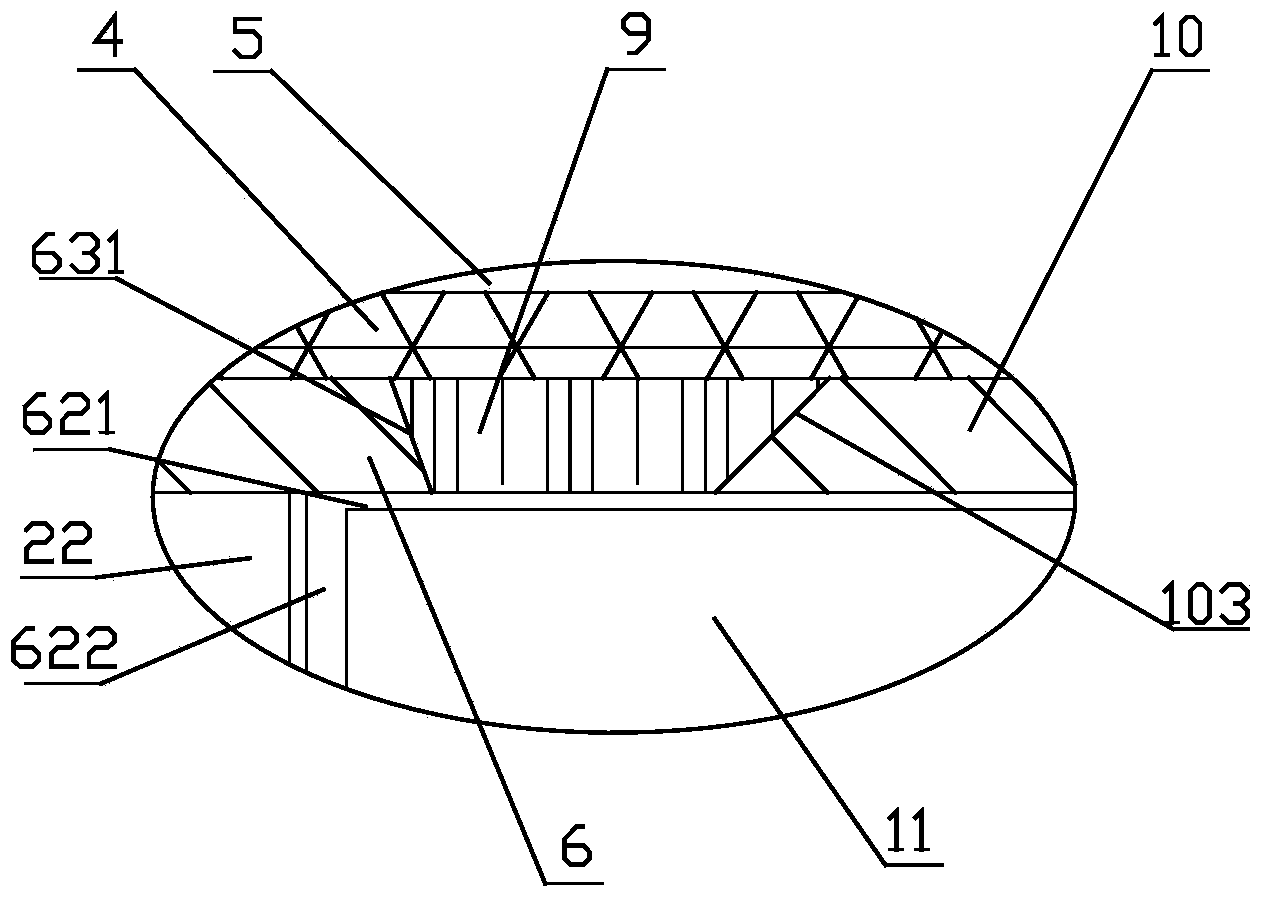
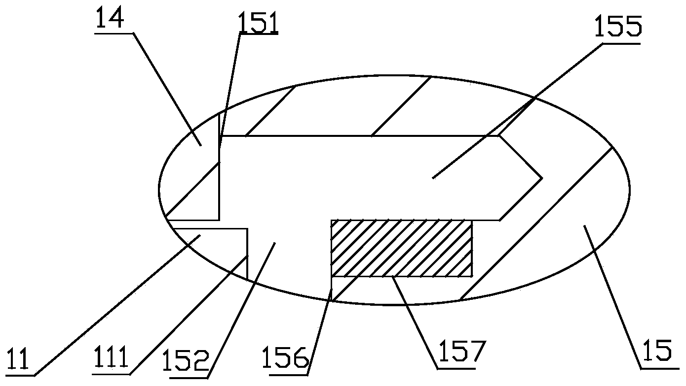
[0028] Embodiment 1, figure 1 A permanent magnet return type high-speed switching electromagnet is given, including a front cover 1, a stopper 2, a casing 3, a coil frame 4, a control coil 5, a leading magnetic sleeve 6, a push rod 7, a limit piece 8, a magnetic isolation Cover 9, rear magnetic guide cover 10, armature 11, flange 12, magnetic isolation sheet 13, magnetic guide sheet 14, rear end cover 15, annular permanent magnet 16 and bearing 17. The above-mentioned block 2, shell 3, front magnetic sleeve 6, rear magnetic sleeve 10, armature 11, flange 12, magnetic sheet 14 and rear end cover 15 are all magnetic guides made of magnetic materials. The magnetic cover 9 is made of non-magnetic material.

[0029] The shell 3 is provided with a cylindrical shell cavity (the left end and the right end of the shell cavity are both connected), the left end of the shell 3 is provided with a front cover 1, the right end of the shell 3 is provided with a magnetic isolation sheet 13, a...


PUM

PropertyMeasurementUnit
thicknessaaaaaaaaaa
lengthaaaaaaaaaa

Abstract

The invention discloses a groove step surface self-returning type electromagnet which comprises a casing and armatures. A horizontally-through casing cavity is arranged in the casing. A front end cover is arranged at the left end of the casing cavity. A magnetic isolation sheet is arranged at the right end of the casing cavity, a magnetic conductive sheet is arranged at the right end of the magnetic isolation sheet, and a rear end cover is arranged at the right end of the magnetic conductive sheet. A stopping block, a front magnetic conductive sleeve, a magnetic isolation sleeve, a rear magnetic conductive sleeve and a flange are sequentially installed in the casing cavity from left to right in a sleeved mode. The front magnetic conductive sleeve, the magnetic isolation sleeve and the rear magnetic conductive sleeve are provided with control coils. A large channel and a small channel are arranged in the rear end cover and are connected in a mutual-communicating mode. The inner cavities are formed among the front magnetic conductive sleeve, the magnetic isolation sleeve, the rear magnetic conductive sleeve, the flange, the magnetic isolation sheet and the magnetic conductive sheet. The right ends of the inner cavities are communicated with the large channel. The armatures are arranged in the inner cavities. An annular permanent magnet is arranged in the large channel.

Description

technical field [0001] The invention relates to an electromagnet, in particular to a self-returning electromagnet with a step surface of a groove. Background technique [0002] A high-speed switching solenoid is an electro-mechanical converter that converts a PWM control amplifier signal into the on and off states of a high-speed switching solenoid. [0003] Invention patent 201010130543.7 discloses a high-speed switch electromagnet with a special structure integrally formed guide sleeve, including a guide sleeve, and an annular trapezoidal groove is arranged in the middle of the guide sleeve. The annular trapezoidal groove is divided into a front basin cone section, The middle bottom and the cone section of the back basin are provided with a ring-shaped permanent magnet at the middle bottom of the ring-shaped trapezoidal groove. Through the ring-shaped permanent magnet, the magnetic flux leakage at the middle bottom is reduced and the electromagnet reaction is accelerated. ...

Claims


Application Information

Patent Timeline
Patent Type & Authority Applications(China)
IPC IPC(8): H01F7/128H01F7/14
Inventor 李其朋李威
Owner ZHEJIANG UNIVERSITY OF SCIENCE AND TECHNOLOGY
Why Eureka
Try Eureka