Card connector

A card connector and card insertion technology, applied in the direction of connection, connecting device components, coupling devices, etc., can solve the problems of hindering miniaturization, increase in size, increase in size, etc., to shorten the overall length and achieve miniaturization , the effect of high shielding effect

Inactive Publication Date: 2014-01-15
SMK CO LTD
View PDF6 Cites 5 Cited by
  • Summary
  • Abstract
  • Description
  • Claims
  • Application Information

AI Technical Summary

Problems solved by technology

[0007] However, in the above-mentioned conventional technology, in order to hold each contact on the molded housing, it is necessary to make the bottom plate portion constituting the bottom of each card insertion portion have a certain thickness, so the card insertion portion is placed on the upper surface of the molded housing. The two recesses of the surface opening are formed in a stepped shape toward the card insertion direction, so they have to be arranged in two layers above and below and staggered in the card insertion direction. Therefore, the dimension of the card connector in the card insertion direction becomes large, become an important factor hindering the miniaturization of the connector as a whole
[0008] In addition, since each card is positioned by abutting against the inner surface of the concave portion formed in the molded case, in order to ensure strength, the wall thickness of the butted part of the molded case has to be increased, and accordingly , the size in the card insertion direction increases, which becomes an important factor hindering miniaturization

Method used


Image

  • Card connector
  • Card connector
  • Card connector

Examples


Embodiment Construction

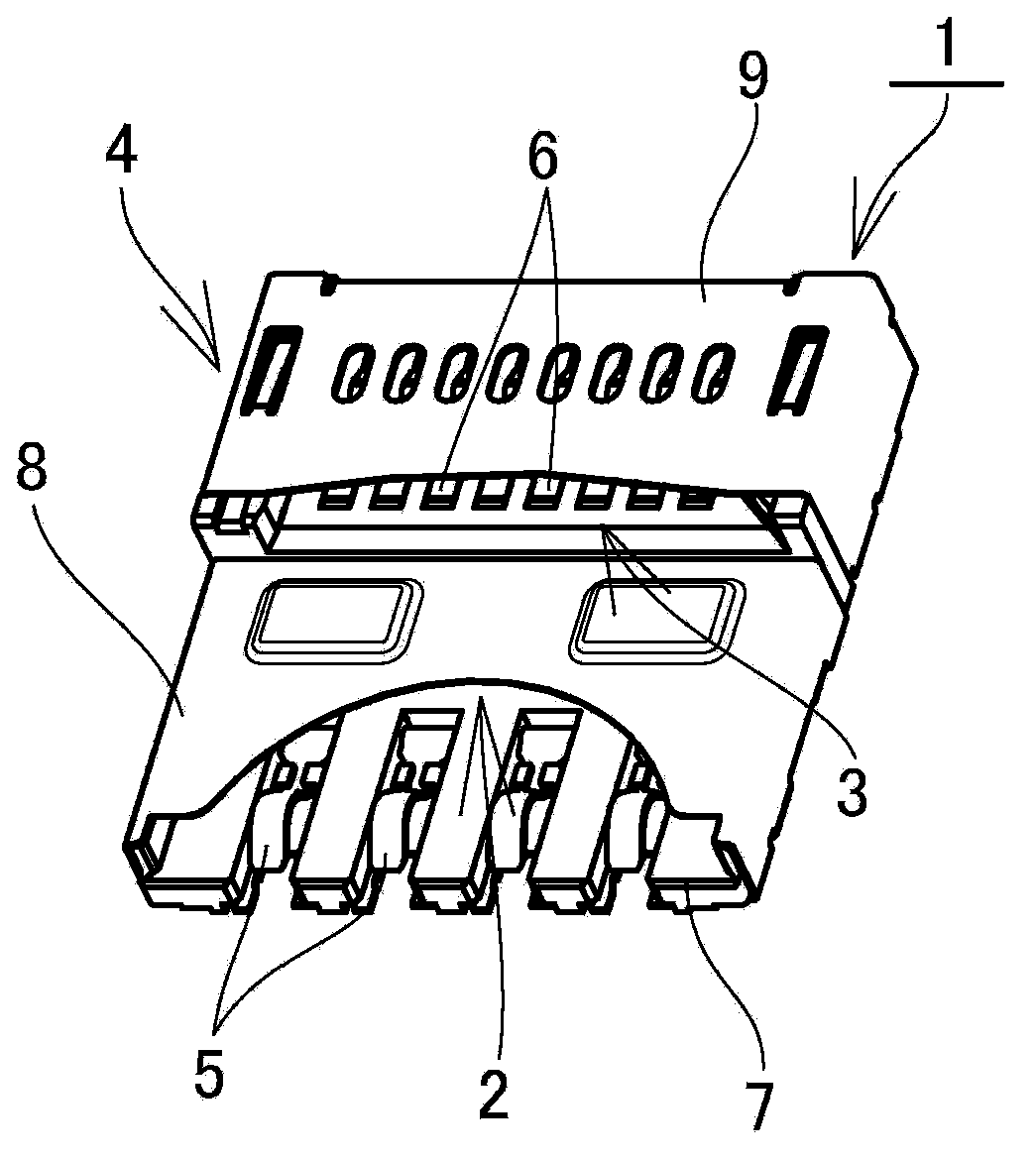
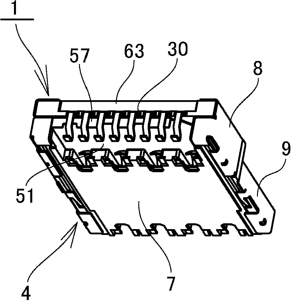
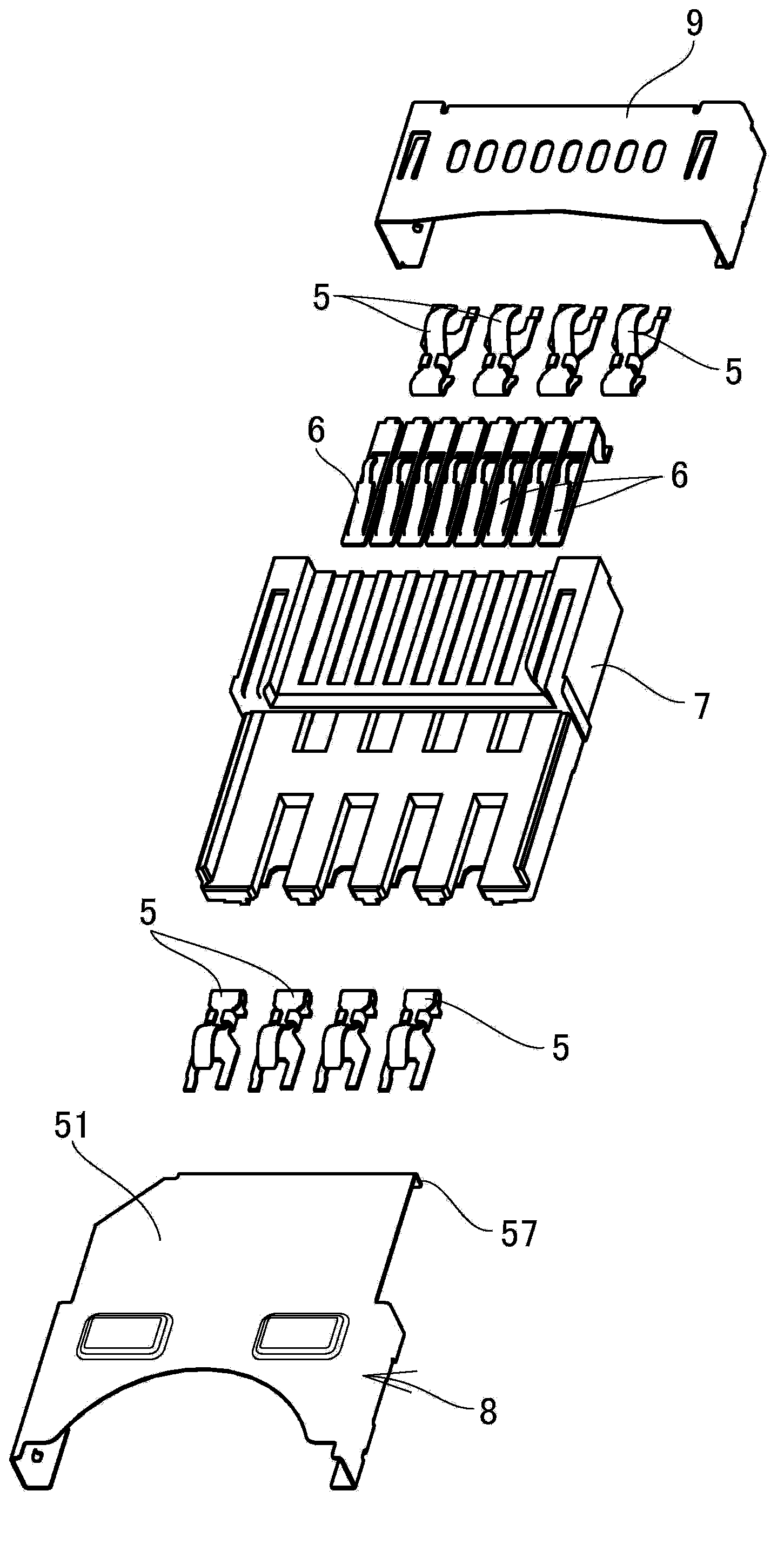
[0039] Next, based on Figure 1~Figure 12The illustrated embodiment illustrates the manner in which the card connector of the present invention can be implemented. In addition, reference numeral 1 in the figure is a card connector, and reference numerals A and B denote cards formed to have the same overall length.

[0040] This card connector 1 has the housing 4 of a plurality of card insertion parts 2, 3 that are arranged in multiple layers for card insertion, and protrudes from the inner bottom of each card insertion part 2, 3 and is inserted into each card insertion part 2, 3. A plurality of contacts 5, 5..., 6, 6... contacted by the signal transmission terminals of the card, through the contacts 5, 5..., 6, 6..., a plurality of cards A, B can be electrically connected to the printed wiring board at the same time connect.

[0041] A card A for example is Figure 5 The small-sized flash memory card shown in (a) is formed in a rectangular shape whose overall length is long...


PUM


Abstract

The invention provides a card connector which can connect with a plurality of cards by multilayer configuration, and the card connector can realize miniaturization and thinness. The card connector is provided with a housing (4) which has a plurality of card inserting portions (2,3) by multilayer configuration, and a plurality of contacts (5,5??,6,6??) contact with signal transmission terminals of cards (A,B) which are inserted in the card inserting portions (2,3), so that a plurality of cards can be connected in parallel configuration. The housing (4) is provided with a mould forming casing (7) made of insulating composite resin, and a lower layer cover component (8) made of metal. The mould forming casing (7) is provided with a lower layer baseplate portion (14) which forms the lower layer card inserting portion (2), and an upper layer baseplate portion (30) of the upper layer card inserting portion (3) which is formed on the lower layer baseplate portion (14) in parallel configuration at interval. The lower layer cover component (8) is provided with a bearing plate portion (51). The bearing plate portion (51) is inserted under the upper layer baseplate portion (30), and supports the lower surface of the upper layer baseplate portion (30).

Description

technical field [0001] The present invention relates to a card connector capable of connecting multiple cards simultaneously. Background technique [0002] In the past, in electronic devices such as mobile phones and digital cameras, there are known devices that use multiple cards, such as IC cards and flash memory cards, as external storage media. As such, two cards are connected to electronic devices at the same time. As a card connector for a printed wiring board, a so-called two-socket type card connector is used. [0003] The two-socket type card connector has two upper and lower layers and a housing in which card insertion portions for card insertion are arranged staggered in the card insertion direction, and a housing that protrudes from the bottom surface of each card insertion portion and is inserted into each card insertion portion. Two cards can be simultaneously connected to the printed circuit board by contacting the signal transmission terminals of each card (...

Claims


Application Information

Patent Timeline
Patent Type & Authority Applications(China)
IPC IPC(8): H01R13/46H01R13/514H01R12/71H01R27/02
Inventor 江尻孝一郎
Owner SMK CO LTD
Why Eureka
Try Eureka