Rail wheel and method for producing a rail wheel

A track and wheel technology, applied in the field of manufacturing track wheels, can solve problems such as insufficient durability

Active Publication Date: 2014-01-15
KNORR BREMSE SYST FUR SCHIENENFAHRZEUGE GMBH
View PDF6 Cites 4 Cited by
  • Summary
  • Abstract
  • Description
  • Claims
  • Application Information

AI Technical Summary

Problems solved by technology

[0006] When achieving a defined and durable contact between the brake disc and the spokes, the following problems arise when using lubricating varnishes known per se: the bonding of the lubricating lacquer layer to the metal surface of the rail wheel or to the contact surface of the spokes is not sufficient durability

Method used


Image

  • Rail wheel and method for producing a rail wheel
  • Rail wheel and method for producing a rail wheel
  • Rail wheel and method for producing a rail wheel

Examples


Embodiment Construction

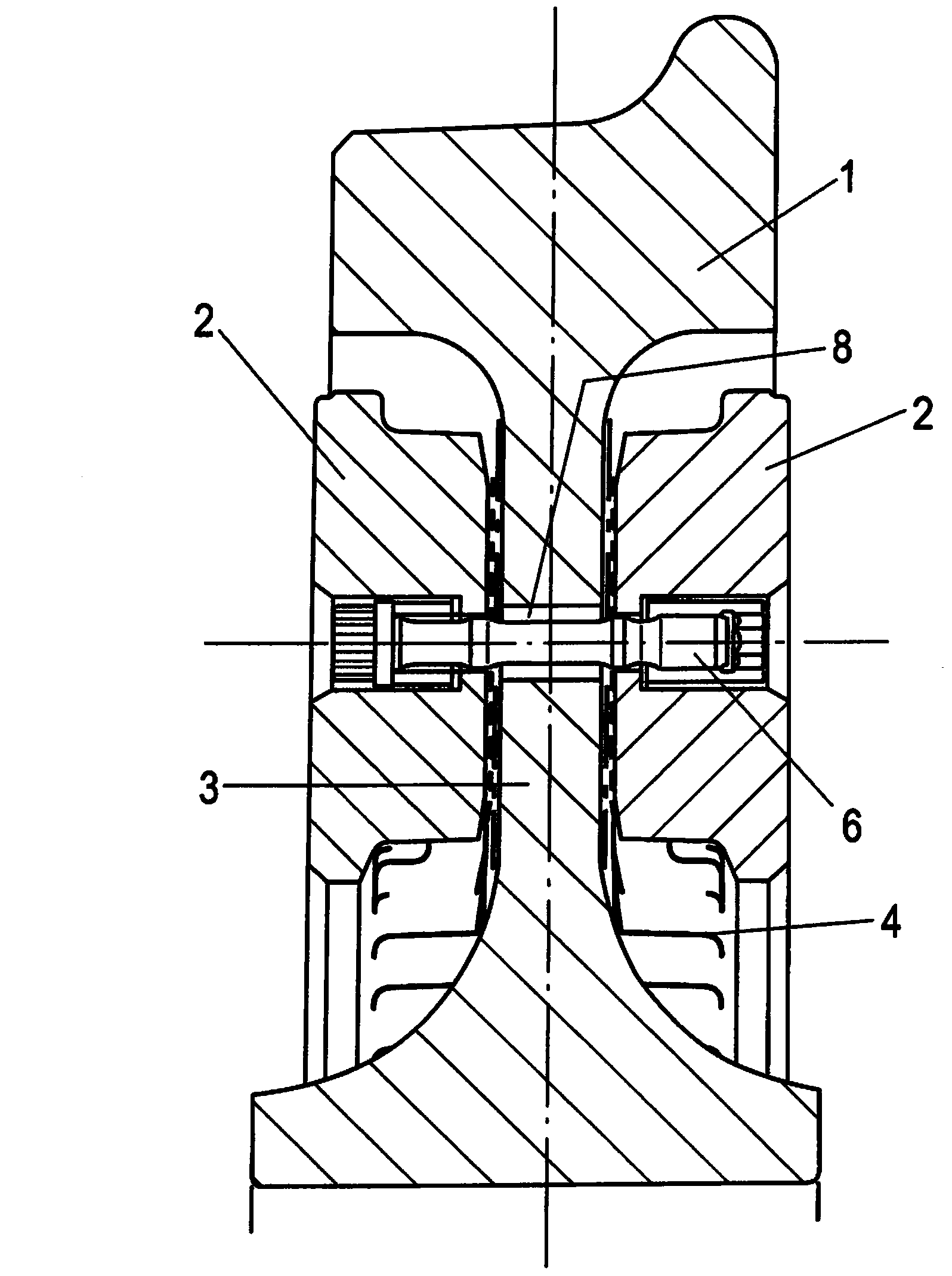
[0031] exist figure 1 and 2 , the friction disc 2 is installed or assembled on the wheel body 1.

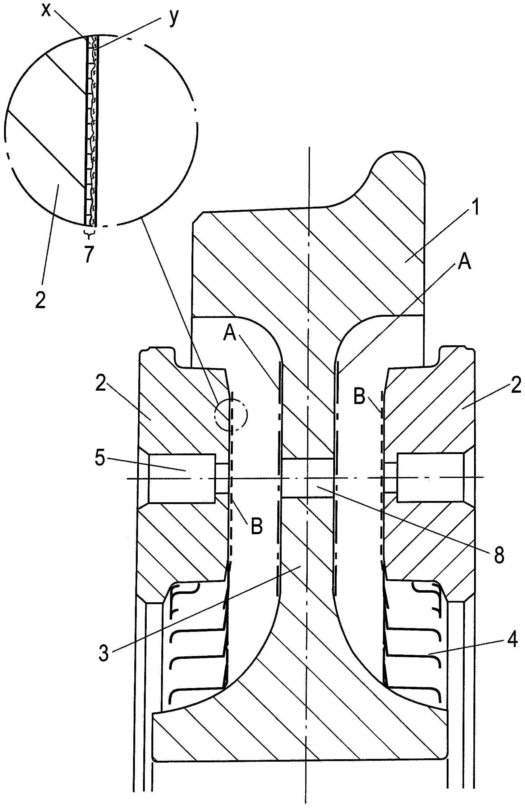
[0032] Here, the spokes 3 of the wheel body 1 have bore holes 8 , which form two circumferential contact surfaces A extending in the radial direction, through which the bolts 6 pass, through which the friction disk 2 and the The wheel body 1 is connected.

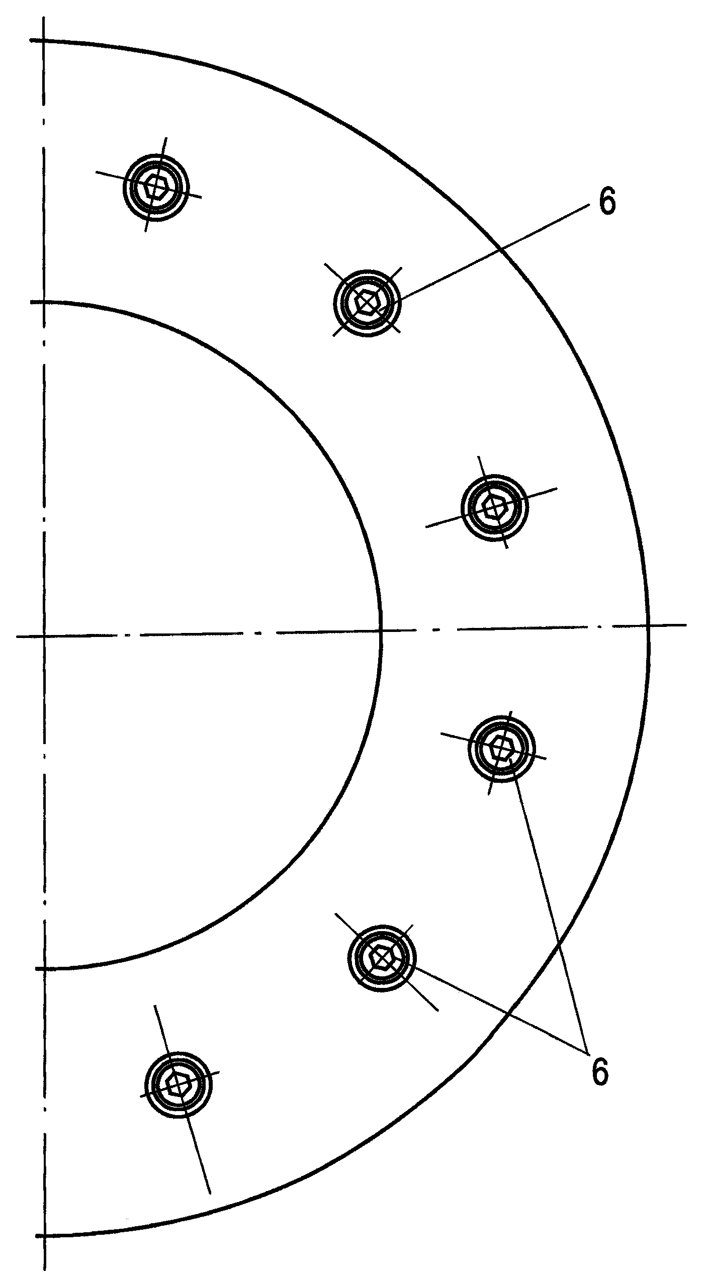
[0033] like image 3 As shown, each of a plurality of bolts 6 distributed at the same angular interval on the circumference passes through a fastening hole 5 of the corresponding friction disk 2, which is opposite to the spoke 3 on the end face, such as the cooling fin 4 of the friction disk. Also forms the abutment area.

[0034] Between the abutment area of ​​the fixing hole 5 and the heat sink 4 and the spokes 3, a coating 7 is arranged to match each friction disc 2, the contact surface A of the spoke 3 is on one side, and the contact surface B of the friction disc 2 On the other side it rests against the coating.

[...


PUM


Abstract

A rail wheel with a wheel body (1) and friction discs (2) connected thereto on both sides by fastening elements, wherein a multi-layer coating (7) is arranged at least between the respective contact surfaces (B) of the friction discs (2) and the contact surfaces (A) of the wheel body (1), with a coating (7) which can be subjected to mechanically and thermally high loading, and a method for producing a rail wheel.

Description

technical field [0001] The invention relates to a rail wheel according to the preamble of claim 1 and a method for producing a rail wheel according to the preamble of claim 14 . Background technique [0002] The connection of the friction disks for braking a rail vehicle with rail wheels can be achieved by screwing the friction disks onto the spokes. The connection must be implemented in such a way that the friction disks can expand when heated and contract again when cooled. This temperature-dependent expansion and contraction leads to a sliding movement of the friction disk on the spokes. These sliding movements occur under relatively high pressure due to the pretension of the bolts. [0003] Friction discs are typically provided with a metal finish, without a durable coating. Here, the disk can be coated with oil, which provides corrosion protection for the friction disk for a limited period of time. However, it is during longer periods of storage, especially in the o...

Claims


Application Information

Patent Timeline
Patent Type & Authority Applications(China)
IPC IPC(8): B60B17/00C25D11/36F16D65/12
CPCB60B17/0006B60B2310/616B60B2900/141B60B2900/561B60Y2200/33C25D11/36F16D65/124Y10T29/49485B60B17/00F16D65/12
Inventor M·尼斯纳C·西格尔
Owner KNORR BREMSE SYST FUR SCHIENENFAHRZEUGE GMBH
Why Eureka
Try Eureka