Tube array hole jet flow jet mixer

A jet mixer, tube-and-tube technology, applied in fluid mixers, mixers, chemical/physical/physicochemical fixed reactors, etc., can solve the problems of poor operational stability of mixers and uneven fluid distribution, and achieve Good mixing effect, efficient mixing process, and the effect of inhibiting side reactions

Active Publication Date: 2014-01-22
SOUTHEAST UNIV
View PDF11 Cites 3 Cited by
  • Summary
  • Abstract
  • Description
  • Claims
  • Application Information

AI Technical Summary

Problems solved by technology

However, when the production scale reaches a certain level, the aspect ratio of the flat channel is relatively large, which will cause uneven distribution of the fluid passing through the jet holes on the flat channel, and the operation stability of the mixer is relatively poor

Method used


Image

  • Tube array hole jet flow jet mixer
  • Tube array hole jet flow jet mixer
  • Tube array hole jet flow jet mixer

Examples


Embodiment 1

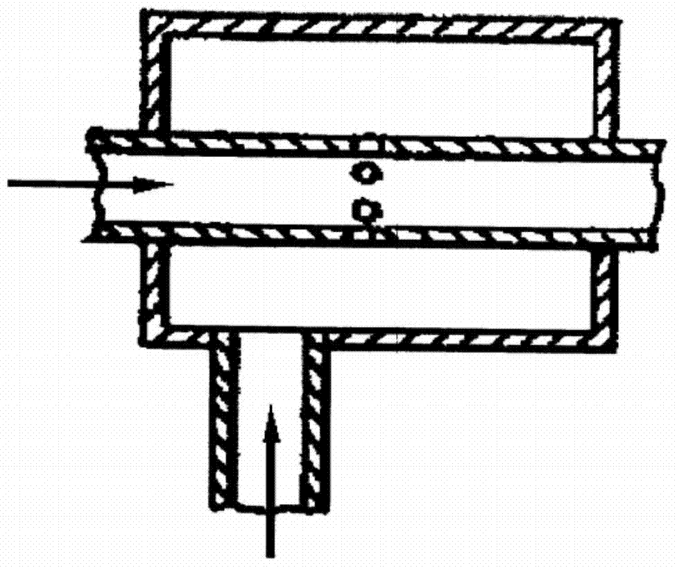
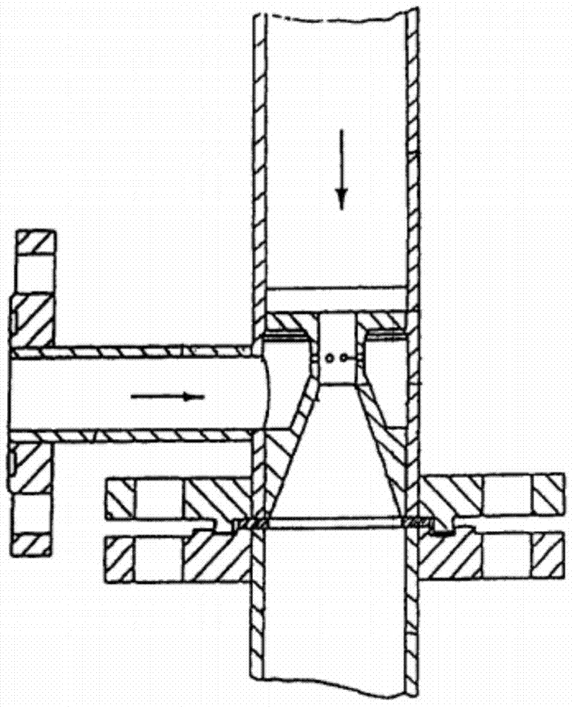
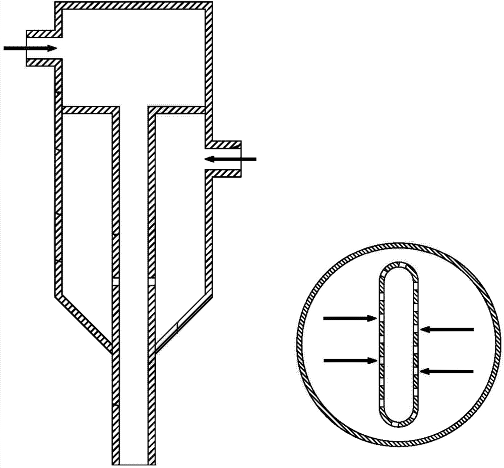
[0038] The tubular orifice jet mixer has the structure as above, and its specifications are: the inner diameter of the shell 1 is 200 mm; the inner diameter of the inner sleeve 3 is 20 mm, the total length of the inner sleeve 3 is 500 mm, and the length of the mixing zone 7 is is 20mm; the arrangement of the inner casing 3 in the housing 1 is as follows Figure 6 In the equilateral triangle arrangement shown, the number of the inner casing 3 is 19, the diameter of the jet hole 4 on the inner casing 3 is 4mm, and the number of the jet holes 4 on each inner casing 3 is 4, The small jet holes 4 are evenly distributed on the same cross section of the inner casing 3 .

[0039] The aqueous solution containing tracer Rhodamine B is continuously injected into the annulus of the mixer from the first feed port 8, and the concentration of Rhodamine B is 100mg / m 3 , the gauge pressure at the first feed port 8 is 3.5bar, and the flow rate of fluid B at the first feed port 8 is 20m 3 / hr....

Embodiment 2

[0042] Adopt the shell-and-tube hole jet mixer of the same structure and size as Example 1, if only the flow at the first feed port 8 is changed to 30m 3 / hr, the rest of the operating conditions remain unchanged.

[0043] The mixing process of the mixer is measured by laser-induced fluorescence technology. At this time, the distance between the transverse section of the two fluids when the mixing degree reaches 95% and the transverse section where the center of the jet hole is located is 26mm. The time corresponding to the mixing process The scale is about 11.2ms.

Embodiment 3

[0045] Using the same structure and size of the tube-type hole jet mixer as in Example 1, only the number of jet holes 4 on the inner sleeve is changed to 6, and the operating conditions are also consistent with Example 1.

[0046] The mixing process of the mixer is measured by laser-induced fluorescence technology. At this time, the distance between the transverse section of the two fluids when the mixing degree reaches 95% and the transverse section where the center of the jet hole is located is 24mm. The time corresponding to the mixing process The scale is about 8.6ms.


PUM


Abstract

The invention provides a tube array hole jet flow jet mixer. The tube array hole jet flow jet mixer comprises a shell (1), fixed plates (2) and inner sleeves (3), wherein a first feed port (8) is arranged on the top of the shell (1), and a second feed port (9) is arranged on the side wall of the shell (1); the fixed plates (2) are arranged on the upper portion of the shell (1), wherein a buffer chamber (5) is formed by the fixed plates (2) and the top of the shell (1) in an enclosed mode, and an annular space is formed by the fixed plates (2) and the side wall and bottom of the shell (1) in an enclosed mode; the inner sleeves (3) are fixed to the fixed plates (2), wherein each inner sleeve (3) is provided with a group of jet flow holes (4), and a mixing zone (7) is arranged under the jet flow holes (4) of each inner sleeve (3). The tube array hole jet flow jet mixer is simple in structure, low in cost, convenient to use, and capable of realizing efficient mixing of two streams of fluid in an extremely short time (at a millisecond level) with mass production capacity, thereby reinforcing main reactions, restraining secondary reactions and improving the selectivity of target products.

Description

technical field [0001] The invention relates to a tubular orifice jet mixer capable of realizing rapid mixing between fluids under large-scale production capacity, and belongs to the technical field of industrial fluid mixing and reaction equipment. Background technique [0002] The rapid mixing and reaction process between materials widely exists in fine chemical industry, pharmaceutical engineering, biochemical industry and other industrial processes. For example, when complex fast parallel competitive reactions or fast serial competitive reactions occur between the reaction materials involved in the chemical production process, since the reaction products or intermediate products will further react with some components in the raw materials, and the characteristic reactions of these reactions The time is at the millisecond level or even less, and the selectivity of the target product depends not only on the kinetic characteristics of the reaction process, but also on the m...

Claims


Application Information

Patent Timeline
Patent Type & Authority Applications(China)
IPC IPC(8): B01F5/02B01F5/04B01J19/26B01J19/24
Inventor 骆培成辛传贤吴俊贾海燕罗小雨
Owner SOUTHEAST UNIV
Why Eureka
Try Eureka