Post-processing technology for SLS workpiece surface

A technology for parts and processes, applied in the field of surface post-treatment of SLS parts, can solve the problems of surface roughness, smoothness and coloring that do not meet the requirements for use, and achieve the effect of improving the optimization rate

Active Publication Date: 2014-01-22
SHENZHEN SUNSHINE LASER & ELECTRONICS TECH CO LTD
View PDF5 Cites 17 Cited by
  • Summary
  • Abstract
  • Description
  • Claims
  • Application Information

AI Technical Summary

Problems solved by technology

[0004] The purpose of the present invention is to provide a post-treatment process for the surface of SLS parts, which has solved the problem in the prior art that the surface roughness, smoothness and coloring cannot meet the requirements of use after the SLS parts are formed.

Method used


Image

  • Post-processing technology for SLS workpiece surface
  • Post-processing technology for SLS workpiece surface
  • Post-processing technology for SLS workpiece surface

Examples


Embodiment 1

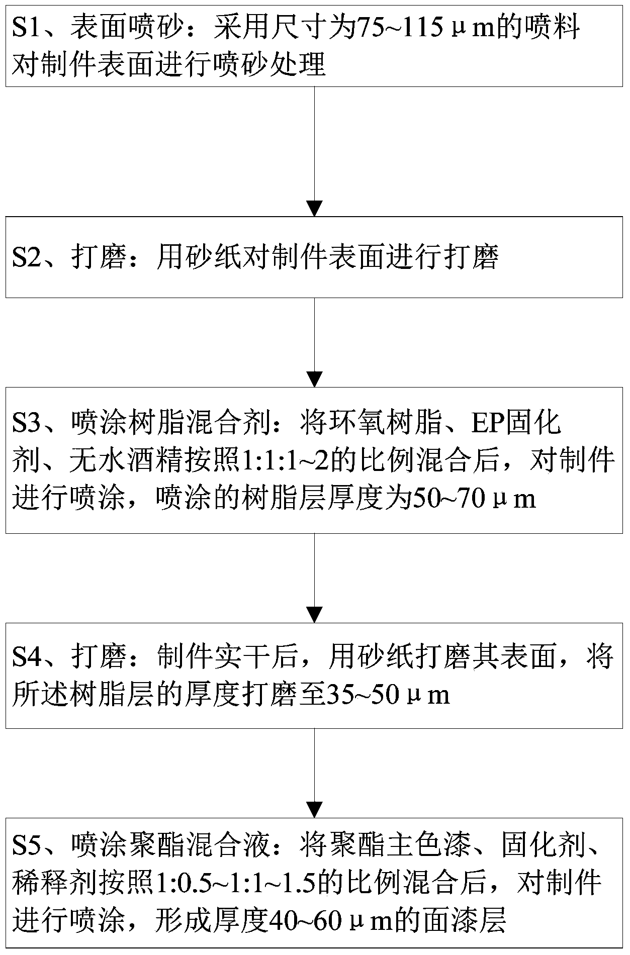
[0033] Select the flat workpiece P1 obtained by sintering by the SLS rapid prototyping system, and process it according to the following steps:

[0034] S1. Sandblasting: blast glass sand with a size of 150 mesh (equivalent to 106 μm) through a sandblasting machine, blast the surface of P1, clean the powder attached to the surface, and impact and grind the burrs on the surface at the same time. , make it slightly deformed, eliminate the residual stress after processing, and obtain a workpiece with a roughness of Ra11.39. The effect is shown in the figure. figure 2 shown;

[0035] S2. Grinding: For the flat processed part P1 after sandblasting, first use No. 180 sandpaper for grinding, and then use No. 360 sandpaper for grinding, until the surface of the flat processed part P1 feels smooth;

[0036] S3. Spraying resin mixture: After mixing epoxy resin, EP curing agent, and anhydrous alcohol according to the ratio of 1:1:1, let it stand for 10 minutes, and spray the flat workp...

Embodiment 2

[0043] Select the flat workpiece P2 obtained by sintering by the SLS rapid prototyping system, and process it according to the following steps: Compared with Example 1, the steps S1 and S2 are the same, and the initial roughness of P2 is also Ra11.39. The difference is:

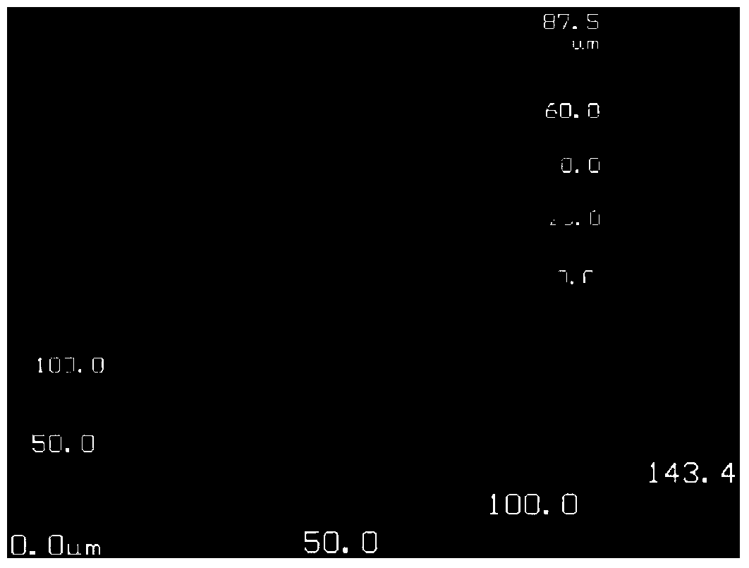
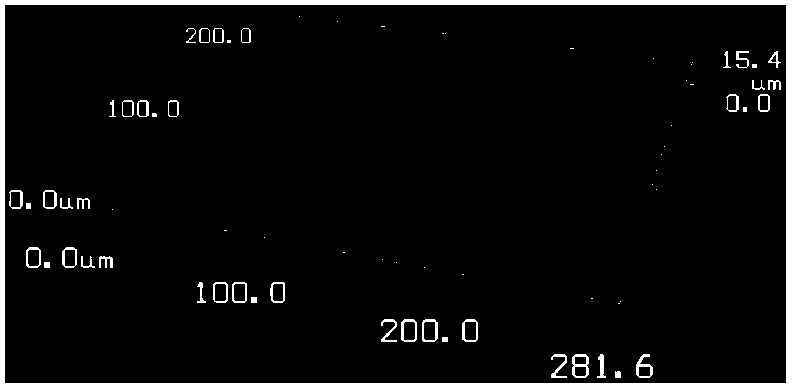
[0044] S3. Spraying resin mixture: After mixing epoxy resin, EP curing agent, and anhydrous alcohol in a ratio of 1:1:2, let it stand for 15 minutes, and spray the flat workpiece P2 with a criss-cross method. After spraying alone in the X direction, spray the Y direction perpendicular to the X direction, and then surface dry for 10 minutes, and the thickness of the sprayed surface resin layer is 50 μm;

[0045] S4. Grinding: After the flat workpiece P2 is dry, grind its surface with No. 360 sandpaper, smooth the burrs not covered by the resin layer, and grind the thickness of the surface resin layer to 40μm, the surface roughness at this time is Ra1.48 , its effect is as follows Figure 4 shown;

[0046] S5...

Embodiment 3

[0050] The difference between this embodiment and Embodiment 1 is only that the size of the blasting material in step S1 is 75 μm. It has been proved by experiments that this embodiment can also obtain substantially the same effect as that of Embodiment 1.


PUM

PropertyMeasurementUnit
thicknessaaaaaaaaaa
thicknessaaaaaaaaaa
thicknessaaaaaaaaaa

Abstract

The invention discloses a post-processing technology for an SLS workpiece surface. The post-processing technology comprises S1, surface abrasive blasting, wherein spraying materials of the size of 75-115 microns are adopted to carry out abrasive blasting processing on the surface of a workpiece; S2, polishing, wherein abrasive paper is used for polishing the surface of the workpiece; S3, resin blending agent spraying, wherein epoxy resin, EP curing agents and anhydrous alcohol are blended according to a ratio of 1:1:1-2, spraying is carried out on the surface of the workpiece, and the thickness of a sprayed resin layer is 50-70 microns; S4, polishing, wherein after the workpiece is dried, the surface of the workpiece is polished through the abrasive paper, and the resin layer is polished to be 35-50 microns thick; S5, polyester paint mixed liquor spraying, wherein after polyester main color paint, curing agents and diluents are blended according to a ratio of 1:0.5-1:1-1.5, spraying is carried out on the workpiece to form a finishing coat layer with a thickness of 40-60 microns. The post-processing technology is adopted to process the nylon SLS workpiece, the surface roughness, surface finish degree and coloring condition of the workpiece can be greatly improved, the strength of the surface of the workpiece is strengthened, and the workpiece is made to meet actual using needs.

Description

technical field [0001] The invention relates to the field of surface treatment, in particular to a surface post-treatment process of an SLS part. Background technique [0002] The selective laser sintering rapid prototyping system - SLS (Selected Laser Sintering), first converts the CAD three-dimensional model into an STL file, slices it according to a certain thickness, and obtains the interface outline of the slice. Then control the laser beam to scan the powder in the solid part of the model, so that the powder particles are melted and bonded to each other, and the outline of the layer is gradually obtained. After the scanning of one layer is completed, the worktable is lowered to the cross-sectional height of one layer, and then the next layer is powdered and sintered, and finally a three-dimensional model is formed. [0003] After the SLS part is formed, there are many pores on the surface, and the surface roughness is about Ra12.5. The roughness, smoothness and colori...

Claims


Application Information

Patent Timeline
Patent Type & Authority Applications(China)
IPC IPC(8): B22F3/24B22F3/105
CPCY02P10/25
Inventor 蔡志祥侯若洪王浩南威
Owner SHENZHEN SUNSHINE LASER & ELECTRONICS TECH CO LTD
Why Eureka
Try Eureka