Dovetail groove turning device

A dovetail groove and turning technology, applied in turning equipment, feeding device, turning equipment, etc., can solve the problems of low processing efficiency and unsuitable for large-scale processing, and achieve the effect of simple structure, high processing efficiency and high turning efficiency.

Inactive Publication Date: 2014-01-22
玉环市佳颂自动化科技有限公司
View PDF7 Cites 5 Cited by
  • Summary
  • Abstract
  • Description
  • Claims
  • Application Information

AI Technical Summary

Problems solved by technology

However, when machining annular dovetail grooves on CNC lathes, the machining efficiency is not high because the tool needs to go through multiple steps, and it is especially not suitable for mass processing.

Method used


Image

  • Dovetail groove turning device
  • Dovetail groove turning device
  • Dovetail groove turning device

Examples


Embodiment Construction

[0026] The following are specific embodiments of the present invention and in conjunction with the accompanying drawings, the technical solutions of the present invention are further described, but the present invention is not limited to these embodiments.

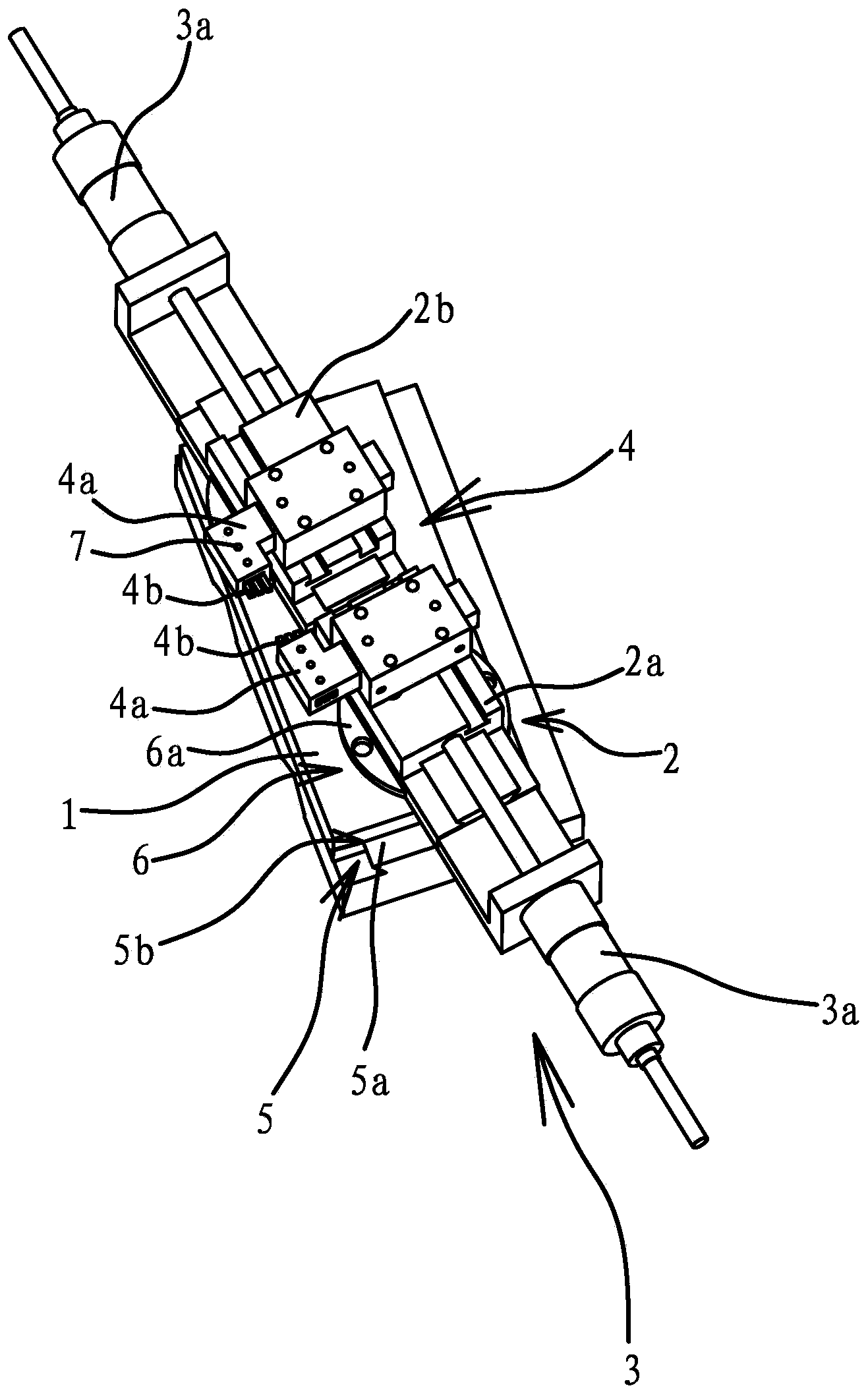
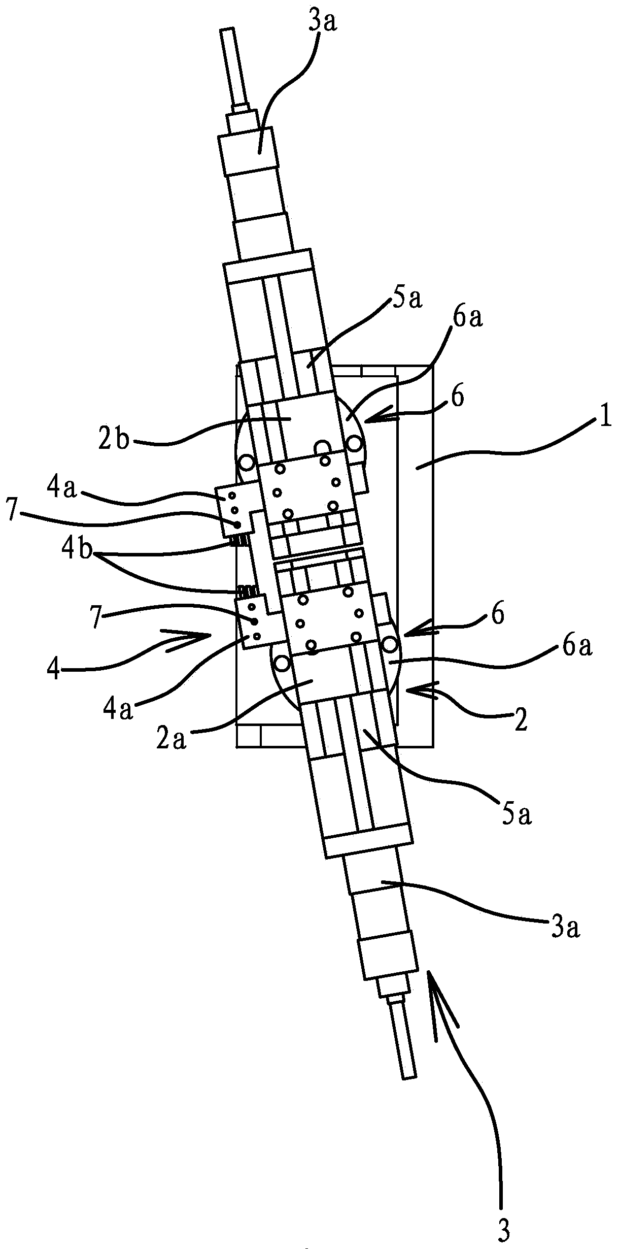
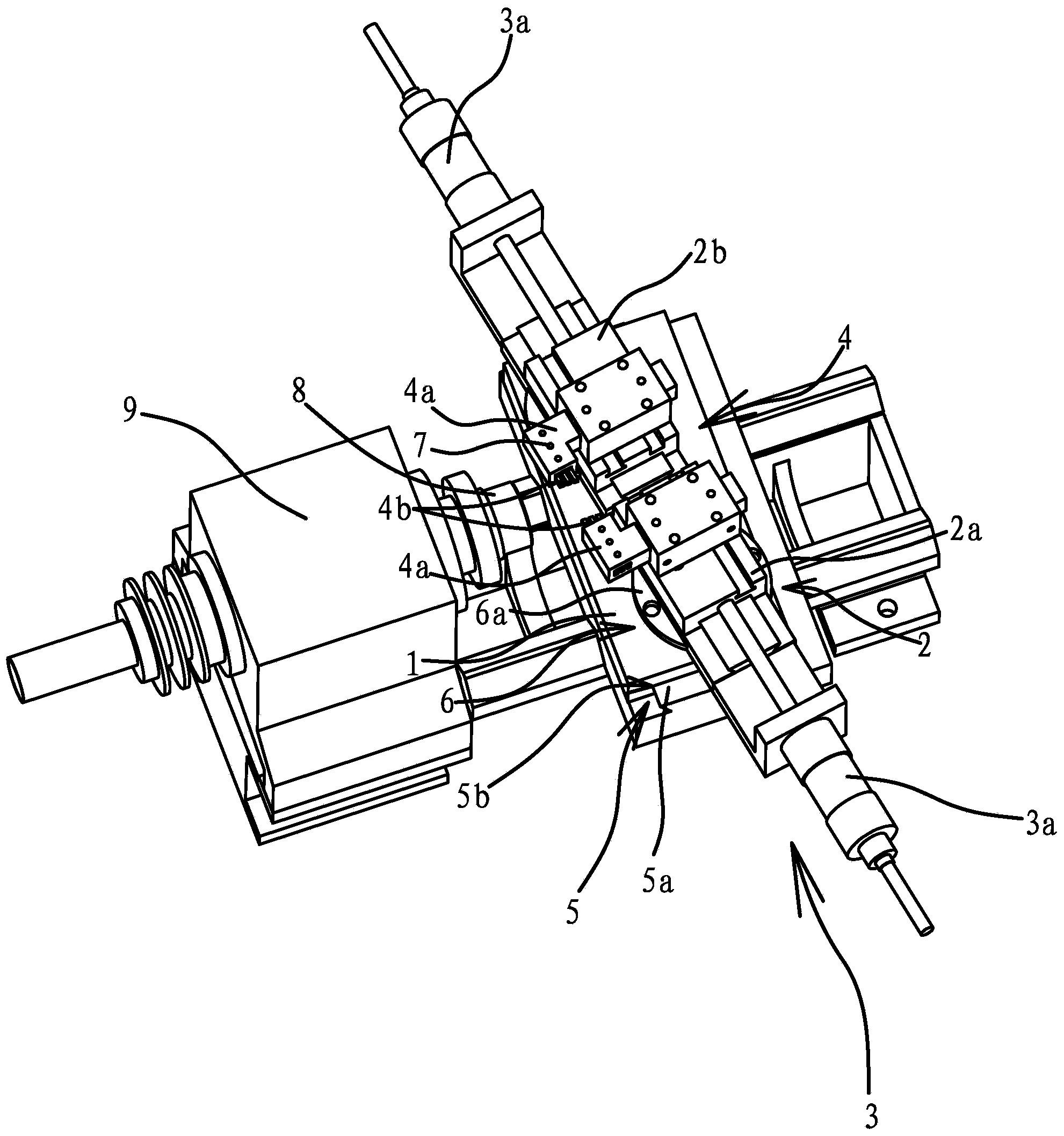
[0027] Such as Figures 1 to 4 As shown, the turning device of the dovetail groove includes a large carriage 1, on which a small carriage 2 is arranged obliquely, and a guide mechanism 5 is provided between the large carriage 1 and the small carriage 2, and the guide mechanism 5 includes a guide rail 5a connected to the large pallet 1 and the guide rail 5a is inclined. The small carriage 2 includes a small carriage one 2a and a small carriage two 2b, the lower sides of the small carriage one 2a and the small carriage two 2b are provided with chute 5b, the small carriage one 2a and the small carriage two 2b The chute 5b is embedded in the guide rail 5a. As another solution, the guide mechanism 5 can also adopt a linear sl...


PUM


Abstract

The invention provides a dovetail groove turning device, and belongs to the technical field of machine tool components. The dovetail groove turning device solves the problem that when an existing lathe is used for machining an annular dovetail groove, machining efficiency is not high, and the dovetail groove is not suitable for mass production. The dovetail groove turning device comprises a big carriage plate, wherein the big carriage plate is provided with small carriage plates arranged in an inclining mode and a driving mechanism which can drive the small carriage plates to move in a reciprocating mode in the inclining direction of the small carriage plates. A tool assembly is arranged on the small carriage plates. The tool assembly comprises two forming tools of a rod shape, wherein the two forming tools are both arranged in parallel in the inclining direction of the small carriage plates, and a gap for a workpiece to pass through is formed between the outer ends of the two forming tools. The dovetail groove turning device has the advantages of being simple in structure, high in machining efficiency and the like.

Description

technical field [0001] The invention belongs to the technical field of machine tool components, and relates to a turning device, in particular to a turning device for a dovetail groove. Background technique [0002] Turning is a method of cutting a workpiece on a lathe by using the rotation of the workpiece relative to the tool. The cutting energy for turning operations is primarily provided by the workpiece rather than the tool. Turning is the most basic and common cutting processing method, which occupies a very important position in production. Turning is suitable for processing rotary surfaces. Most workpieces with rotary surfaces can be processed by turning methods, such as inner and outer cylindrical surfaces, inner and outer conical surfaces, end faces, grooves, threads, and rotary forming surfaces. The tools used are mainly forming knives. [0003] When machining the annular dovetail groove of the side wall of the rod-shaped workpiece, it is generally processed on ...

Claims


Application Information

Patent Timeline
Patent Type & Authority Applications(China)
IPC IPC(8): B23B5/00B23B21/00B23Q5/34
CPCB23B5/00B23Q1/26B23Q5/34
Inventor 杨建龙谢建军
Owner 玉环市佳颂自动化科技有限公司
Why Eureka
Try Eureka