Automatic workpiece turning process based on manipulator

A technology of manipulators and automatic vehicles, which is applied in metal processing machinery parts, manufacturing tools, metal processing equipment, etc., can solve problems such as personnel replacement, and achieve the effect of simplifying alignment steps, saving grasping space, and simplifying control difficulty.

Active Publication Date: 2022-08-05
四川竞本科技有限公司
View PDF8 Cites 0 Cited by
  • Summary
  • Abstract
  • Description
  • Claims
  • Application Information

AI Technical Summary

Problems solved by technology

[0003]In order to solve the problem of personnel replacement in the common turning operation of the top surface, ground and side of the workpiece in the prior art, this solution provides a robot-based workpiece automatic Turning process

Method used


Image

  • Automatic workpiece turning process based on manipulator
  • Automatic workpiece turning process based on manipulator
  • Automatic workpiece turning process based on manipulator

Examples


Embodiment 1

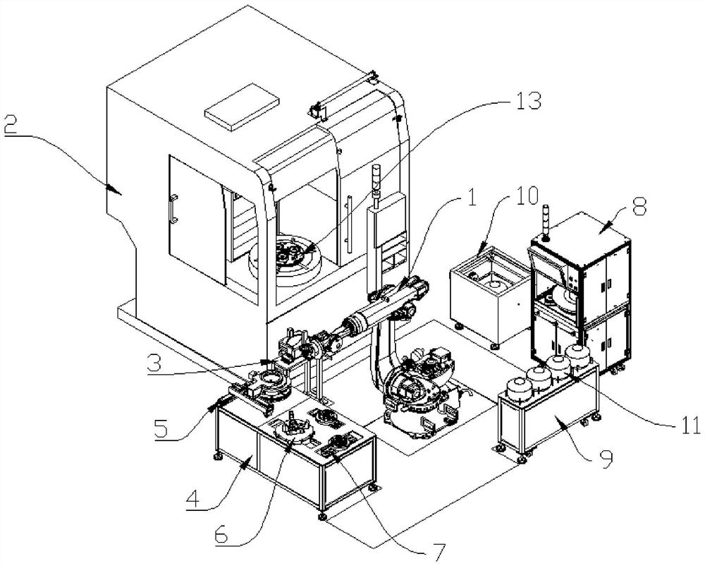
[0057] like Figure 1 to Figure 15 As shown, in order to meet the needs of automatic turning processing of the above-mentioned workpiece 11, the present embodiment designs a turning processing device, which includes a station circulation mechanism and different stations around the station circulation mechanism. The workpiece 11 will be replaced by the station The circulation mechanism grabs and realizes the circulation of the workpiece 11 between different stations, and the different stations are used for corresponding processing of the workpiece 11 .

[0058] In this embodiment, the station circulation mechanism adopts the manipulator 1, and the manipulator 1 is controlled by a corresponding industrial computer. The specific control program is provided by the supplier of the manipulator 1, which will not be repeated here.

[0059] A storage station, a cleaning station, a turning station, a rotation station, an alignment station, a tool placement station and a visual inspectio...

Embodiment 2

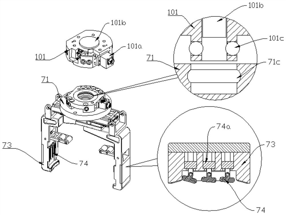
[0061] On the basis of the structure of the first embodiment, in order to realize the rapid replacement of the tooling claw 7 by the manipulator 1 and the manipulation of the tooling claw 7 , the present embodiment designs the tooling claw 7 with the following structure.

[0062] The tooling claw 7 of this embodiment includes a movable connector 71 and a claw assembly. The movable connector 71 is connected to the handle of the claw assembly. The manipulator 1 is provided with a fixed connector 101 matching the movable connector 71. Therefore, the jaw assembly can be quickly assembled on the manipulator 1 .

[0063] An electrical connection male 71a is provided on one side of the movable connector 71, and the connection direction of the two is the same; an electrical connection female 101a is provided on one side of the fixed connector 101, and the connection direction of the two is the same; the dynamic connection When the head 71 is connected to the fixed connection head 101,...

Embodiment 3

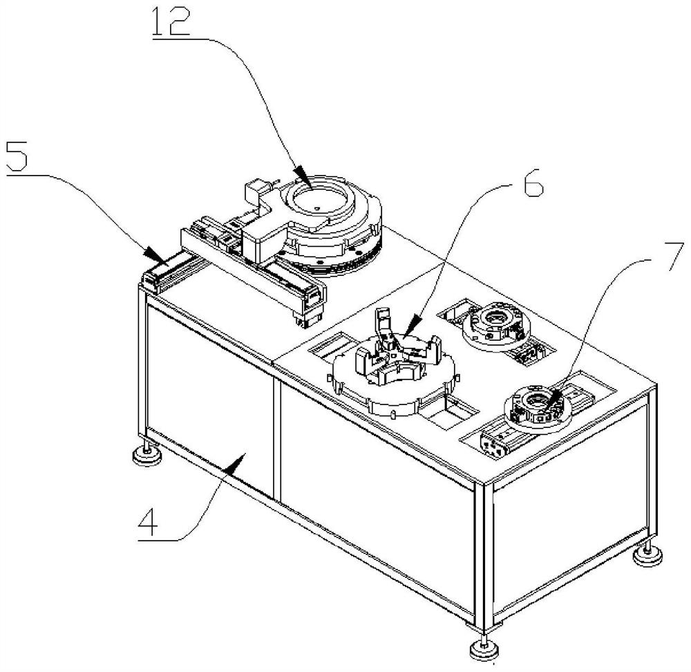
[0071] On the basis of the structure of Embodiment 1, in order to ensure the determination of the center position of the workpiece 11 when turning on the vertical lathe structure 2, it is often necessary to place the workpiece 11 on a carrier for turning, and this embodiment is aimed at this. One problem, the pneumatic chuck 6 and the suction cup assembly 12 are designed that can be used as a carrier for the workpiece 11 .

[0072] The pneumatic chuck 6 includes a chuck positioning plate 62 and a three-jaw pneumatic clamping jaw 61. The chuck positioning plate 62 is disc-shaped, and the three-jaw pneumatic clamping jaw 61 is fixed on the top surface of the chuck positioning plate 62 and is used for the workpiece 11. A plurality of chuck positioning feet 63 are arranged on the bottom surface of the chuck positioning plate 62; a chuck pressure maintaining joint 64 is arranged at the center of the bottom surface of the chuck positioning plate 62, and the chuck pressure maintaining...


PUM


Abstract

The invention belongs to the technical field of automatic turning equipment, and particularly relates to an automatic workpiece turning process based on a manipulator, which comprises a blank rough machining procedure and a semi-finished product finish machining procedure. The manipulator is used as the center and matched with different stations, in the turning process of the workpiece, the workpiece can flow in the different stations, the top face, the bottom face and the side face of the workpiece can be automatically machined under automatic control and cooperation of all equipment, machining of the workpiece from a blank to a semi-finished product is automatically achieved, and the machining efficiency of the workpiece is improved. Turning machining from a semi-finished workpiece to a finished workpiece can also be achieved; the problems of manpower consumption and cost caused by manual duty and manual replacement in the turning process of batch workpieces are solved, and by means of automatic turning, the efficiency is effectively improved, and manpower and material resources are saved.

Description

technical field [0001] The invention belongs to the technical field of automatic turning processing equipment, and in particular relates to an automatic workpiece turning process based on a manipulator. Background technique [0002] With the advancement of science and technology, automatic turning technology has also emerged, and to realize automatic turning, one of the important links is to realize the flow of workpieces between various stations and process steps, and with the level of robot automation It is necessary to design a turning processing device and a corresponding turning process that is centered on the manipulator and can perform surface turning on the workpiece, so as to improve the turning processing in the process of realizing the batch operation of the workpiece. SUMMARY OF THE INVENTION [0003] In order to solve the problem that personnel need to be replaced in the joint turning operation of the top surface, the ground and the side surface of the workpie...

Claims


Application Information

Patent Timeline
IPC IPC(8): B23Q3/06B23Q11/00
CPCB23Q3/06B23Q11/00
Inventor 王亮
Owner 四川竞本科技有限公司
Why Eureka
Try Eureka