Engineering vehicle chassis brake control system and crane

A technology for chassis braking and engineering vehicles, applied in the direction of brakes, brake components, vehicle components, etc., can solve the problems of poor driving braking stability, weak emergency braking ability, weakened braking ability, etc., and achieve enhanced braking ability , Improving braking performance and sufficient air supply

Active Publication Date: 2014-01-22
XUZHOU HEAVY MASCH CO LTD
View PDF8 Cites 3 Cited by
  • Summary
  • Abstract
  • Description
  • Claims
  • Application Information

AI Technical Summary

Problems solved by technology

[0018] In the brake control circuit, port 21 of the foot brake valve 51 is connected to the front part of the axle brake air circuit of the whole machine, and port 22 is connected to the rear part of the axle brake air circuit. The pressure of the chamber air outlet (port 22) is generally 0.2 to 0.3 bar. When braking, the front axle brakes before the rear axle brake. The inertial force causes the vehicle to lean forward, and the braking stability of the vehicle is poor.
[0019] In summary, for all-terrain cranes, the following methods are used: figure 1 In the existing braking control method shown, all the air chambers of the two bridges are supplied with air from the air outlet 22 of the foot relay valve 53 during the service braking, resulting in insufficient air supply during braking and weakened braking ability
And the two parking brake control axles share a manual relay valve 540, so the emergency braking capability is relatively weak
In the service braking, the front part of the axle is braked before the rear part of the axle is braked, and the braking stability of the whole machine is poor

Method used


Image

  • Engineering vehicle chassis brake control system and crane
  • Engineering vehicle chassis brake control system and crane

Examples


Embodiment Construction

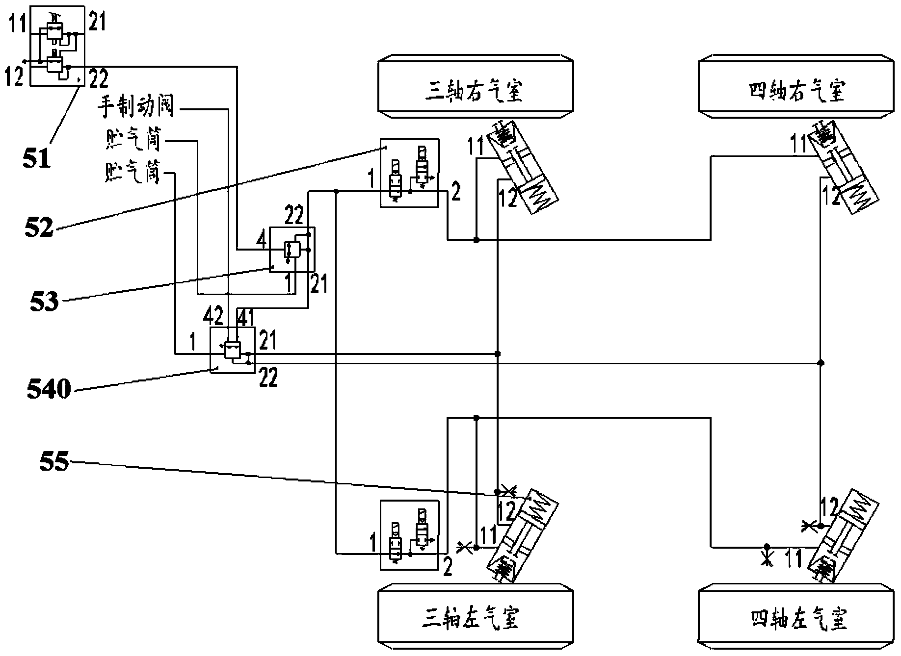
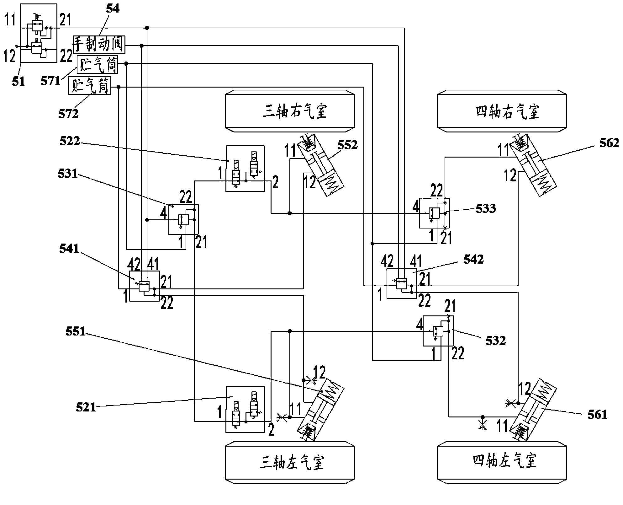
[0059] Below you can refer to the accompanying drawings Figure 1 ~ Figure 2 And the content of the text to understand the content of the present invention and the differences between the present invention and the prior art. The technical solution (including the preferred technical solution) of the present invention will be further described in detail below by way of the accompanying drawings and listing some optional embodiments of the present invention. It should be noted that: any technical feature and any technical solution in this embodiment are one or more of a variety of optional technical features or optional technical solutions. Citing all the alternative technical features and alternative technical solutions of the present invention, it is not convenient for the implementation of each technical feature to emphasize that it is one of the optional multiple implementation modes, so those skilled in the art should know that: Replace any technical means provided by the p...


PUM


Abstract

The invention discloses an engineering vehicle chassis brake control system and a crane, and relates to the technical field of engineering vehicles. The technical problem that braking capacity in the prior art is poor is solved. The engineering vehicle chassis brake control system comprises a foot brake valve, a first foot relay valve, a three-shaft left brake chamber, a three-shaft right brake chamber and a first air tank, and an air inlet of the first foot relay valve is communicated with an air outlet of the first air tank. One of two air outlets of the first foot relay valve is communicated with a travelling brake airflow inlet of the three-shaft left brake chamber. The other of the two air outlets of the first foot relay valve is communicated with a travelling brake airflow inlet of the three-shaft right brake chamber. The crane comprises a rear axle brake air path, and the rear axle brake air path comprises the engineering vehicle chassis brake control system. The engineering vehicle chassis brake control system and the crane are used for improving the brake performance of the chassis brake control system of the crane.

Description

technical field [0001] The invention relates to the technical field of engineering vehicles, in particular to an engineering vehicle chassis braking control system and a crane equipped with the engineering vehicle chassis braking control system, especially an all-terrain crane equipped with the engineering vehicle chassis braking control system. Background technique [0002] At present, the main methods used in the braking system are mainly divided into mechanical braking, hydraulic braking and pneumatic braking according to the transmission mode of braking energy. [0003] 1) Mechanical brake: It is adopted because of its large braking torque, high reliability and good effect, but this kind of braking structure is complex, and its manipulation sensitivity and quick response are poor. [0004] 2) Hydraulic brake: It has the characteristics of light and labor-saving operation, quick response, simple structure, and small mass. However, the hydraulic brake torque is unstable an...

Claims


Application Information

Patent Timeline
Patent Type & Authority Applications(China)
IPC IPC(8): B60T15/02
Inventor 马云旺马飞赵留福靳少杰
Owner XUZHOU HEAVY MASCH CO LTD
Why Eureka
Try Eureka