Observation device for cell biological behaviors in direct current electric field

A DC electric field and observation device technology, applied in biochemical cleaning devices, enzymology/microbiology devices, tissue cell/virus culture devices, etc., can solve the problems of many barriers, large distances, and great influence on cells. To achieve the effect of improving stability

Inactive Publication Date: 2014-12-10
SECOND MILITARY MEDICAL UNIV OF THE PEOPLES LIBERATION ARMY
View PDF4 Cites 0 Cited by
  • Summary
  • Abstract
  • Description
  • Claims
  • Application Information

AI Technical Summary

Problems solved by technology

The problem in the prior art is that for the same cell, it is necessary to conduct experiments under the conditions of various current densities, and only a different height of the isolation bank can be changed to increase or decrease the height of the channel to achieve different current densities. , but if the cultured cells are moved from one culture dish to another, the cells need to be digested from the adherent state first, and then moved to another culture dish. In this process, not only the shape of the cells Changes have occurred, and the wall needs to be re-attached, and the digestion process itself has damage to the cells, and the experimental conditions cannot achieve the purpose of uniformity
The way to solve this problem in the previous technology is to culture the cells on the cover glass for observation, and move the cover glass and the cells on it to a new petri dish together when moving, but the process of taking out the cells is not only easy to cause bacterial contamination , and because the cells enter the air environment from the environment of the culture medium, the air will also have some stimulating effects on the cells, so it has a great impact on the cells
In addition, since cells often need to be observed under a confocal microscope, planting cells on a separate cover glass will cause the distance between the lens of the confocal microscope and the cells to be too large, and the distance between the lens of the confocal microscope and the cells will be too large. There are too many barriers in between, resulting in unclear imaging

Method used


Image

  • Observation device for cell biological behaviors in direct current electric field
  • Observation device for cell biological behaviors in direct current electric field
  • Observation device for cell biological behaviors in direct current electric field

Examples


Embodiment 1

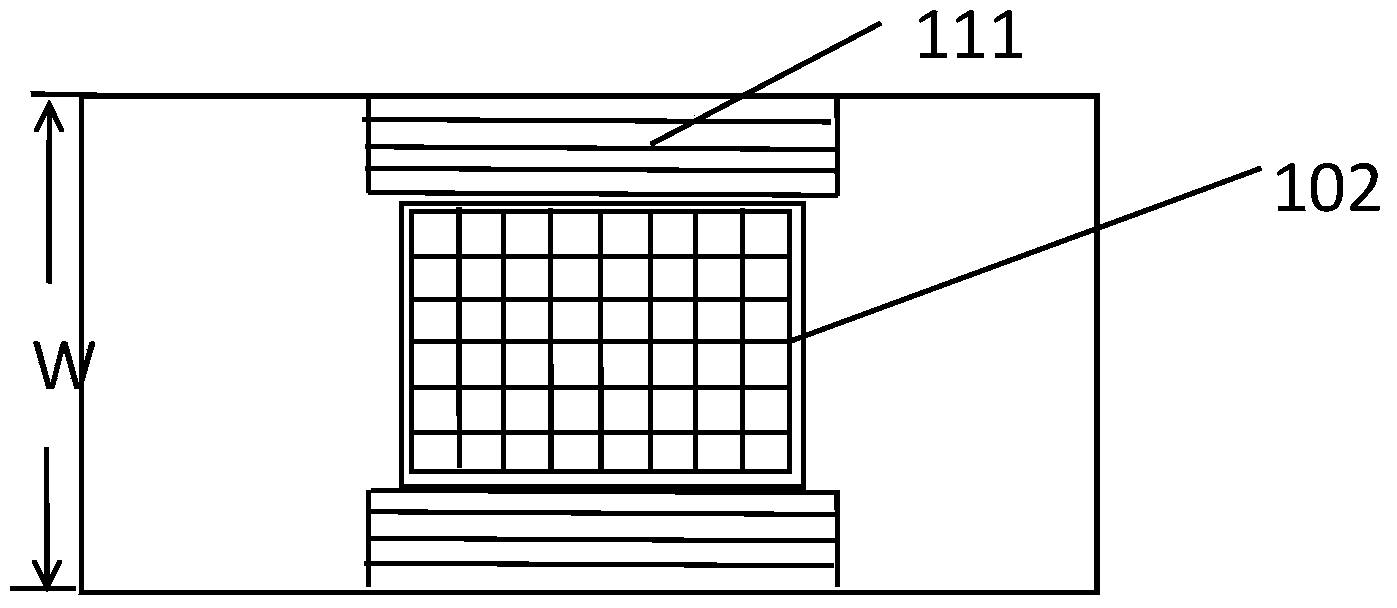
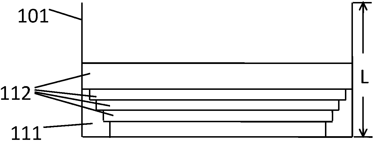
[0034] figure 2 It is a top view of the base groove in Embodiment 1 of the present invention; image 3 It is a side view of the base tank in Embodiment 1 of the present invention; Figure 4 It is the front view of the cell carrying part in Example 1 of the present invention; Figure 5 It is a top view of the top cover in Embodiment 1 of the present invention.

[0035] like Figure 2-4As shown, the cell carrying part is composed of a base tank 101 , a plurality of cover plates 112 (four in this embodiment) and a top cover 103 . Wherein the base tank 101 is a rectangle, and the middle part is provided with an observation area 102 drawn with a grid. The opposite sides of the observation area 102 are provided with stepped structures 111 of the same size, each with 4 steps, and the first step is 200 microns away from the bottom surface of the base tank 101. , the fourth step is 400 microns away from the bottom surface of the substrate groove 101 . like image 3 As shown, the...

Embodiment 2

[0040] Image 6 It is a top view of the base groove in Embodiment 2 of the present invention; Figure 7 It is a side view of the base tank in Embodiment 2 of the present invention; Figure 8 It is the front view of the cell carrying part in Example 2 of the present invention; Figure 9 It is a top view of the top cover in Embodiment 2 of the present invention.

[0041] like Figures 6 to 8 As shown, in this embodiment, the cell carrying part is composed of a base tank 101 , a spacer 121 , a traction assembly 122 and a top cover 108 . The base tank 101 is rectangular, and an observation area 102 drawn with grid lines is set in the middle. An observation chamber is formed between the observation area 102 and the spacer 121 disposed above it. The spacer 121 is a rectangular column whose width is equal to the width of the substrate groove 101 . The spacer 121 is connected to the traction assembly 122 , and the traction assembly 122 drives the spacer 121 to move perpendicular...


PUM


Abstract

The invention provides an observation device for cell biological behaviors in a direct current electric field. The observation device is used for observing the biological behaviors of cells in the direct current electric field and comprises an electric field generation part, a cell bearing part, a current monitoring part, a fluid exchange part, an image recording part, a control part and a plurality of cover plates used for adjusting the height of a culture medium on the cells. An observation area and two corresponding step structures are arranged in the cell bearing part. An observation area and two identical step structures are arranged in a middle area of a base tank, wherein the two corresponding step structures are arranged on the two sides of the observation area, the number of steps is m, and distances between the steps at the same level of the two step structures are respectively l1, l2... and lm. The number of the cover plates is n, and the widths of the cover plates are respectively w1, w2... and wn, wherein the width wi of the cover plate i (1<=i<=n) is greater than or equal to li and less than or equal to li+1. By means of the observation device, the height of the culture medium on the cells can be changed more quickly and can be adjusted conveniently at the time of an experiment.

Description

technical field [0001] The invention relates to the field of cell biology, in particular to the field of observation of biological behavior of cells. Background technique [0002] DC electric fields have effects on tissue formation, inflammatory response, and nerve injury repair. Therefore, the behavioral observation of cells under DC electric field in vitro has become a necessary research method. [0003] When studying the behavior of cells in a DC electric field, it is necessary to make a special culture dish. The traditional manufacturing method is to first make a square glass well; Leave a certain distance between the glass slides to form a channel, use 3140 silica gel to stick two coverslips side by side on the bottom of the culture dish, leave a certain distance between the two coverslips to form a channel, use 3140 silica gel on the bottom of the culture dish along the two sides Build two isolation dikes on the upper and lower edges of the block cover plate (the cha...

Claims


Application Information

Patent Timeline
IPC IPC(8): C12M3/04C12M1/42C12M1/36C12M1/34
CPCC12M35/02C12M41/00C12M41/26
Inventor 徐大波付强王小平刘彦斌宋绍军李军卢蕾
Owner SECOND MILITARY MEDICAL UNIV OF THE PEOPLES LIBERATION ARMY
Why Eureka
Try Eureka