Rotary drilling rig control rotary hydraulic circuit system

A technology for rotary drilling rigs and hydraulic circuits, applied in the direction of rotary drilling rigs, rotary drilling, mechanical equipment, etc., can solve the problems of low generalization, high technical difficulty, and replacement, and achieve high universality and low technical difficulty , easy to achieve effect

Active Publication Date: 2016-06-01
QINGDAO LOVOL EXCAVATOR
View PDF9 Cites 3 Cited by
  • Summary
  • Abstract
  • Description
  • Claims
  • Application Information

AI Technical Summary

Problems solved by technology

Although the slewing speed is reduced during the slewing action, part of the flow output by the main pump 4 still flows through the middle damping oil channel of the spool 2.3 of the slewing joint and flows back to the oil tank, as figure 2 As shown, the output flow of the main pump 4 can meet the rotation demand at point C, but this technical solution works at point D, and the excess flow is wasted in the form of heat energy
[0009] 2. High technical difficulty and increased cost
Due to technical limitations, it is necessary to repeatedly test and process to achieve the required value. Some models require a low rotation speed and cannot be processed to the required flow value.
If the main engine factory replaces the spool by itself, it will increase the cost and easily pollute the system
[0010] 3. Low generalization
Once the spool is processed, it can only be used with matching engines, main pumps, main valves, slewing motors, reducers, and slewing supports. If the configuration changes, the spool needs to be replaced
[0011] 4. Poor stability, greatly affected by external factors

Method used


Image

  • Rotary drilling rig control rotary hydraulic circuit system
  • Rotary drilling rig control rotary hydraulic circuit system
  • Rotary drilling rig control rotary hydraulic circuit system

Examples


Embodiment Construction

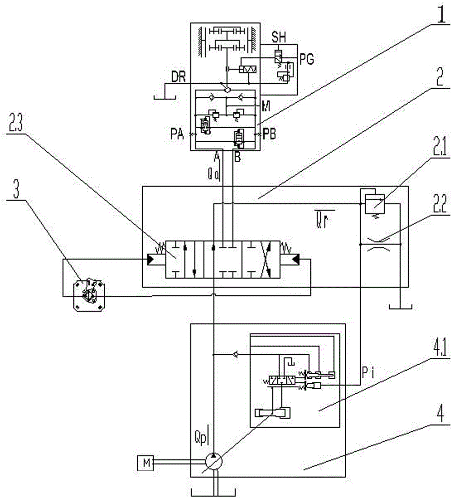
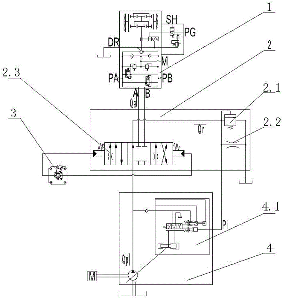
[0035] Examples such as Figure 4 As shown, a rotary drilling rig control rotary hydraulic circuit system includes a main pump 4, the main pump 4 is provided with a variable mechanism 4.1, the main pump 4 is connected with a main control valve 2 through a pipeline, and the main control A rotary spool 2.3 is installed in the valve 2, and the rotary spool 2.3 is respectively connected with the pilot handle 3 and the rotary motor 1 through the pipeline;

[0036] The main control valve 2 is also equipped with a relief valve 2.1, the oil inlet side of the relief valve 2.1 communicates with the rotary valve core 2.3 through the oil passage, and the oil inlet side of the relief valve 2.1 communicates with the variable mechanism 4.1 through the pipe The road connects.

[0037] A rotary deceleration device 5 is installed on the communication pipeline between the overflow valve 2.1 and the variable mechanism 4.1, and the rotary deceleration device 5 is communicated with a pilot oil inl...


PUM


Abstract

The invention discloses a rotation controlling hydraulic circuit system for a rotary drilling rig. The rotation controlling hydraulic circuit system for the rotary drilling rig comprises a main pump. The main pump is communicated with a main control valve through a pipeline and the main control valve is respectively communicated with a guiding handle and a rotary motor through pipelines; a rotation speed reducing device is further communicated between the main pump and the main control valve through pipelines. According to the technical scheme, when the rotary drilling rig is free of actions or free of other actions except for rotation, an electromagnetic valve in the rotation speed reducing device is not powered on, and feedback pressure generated by a feedback oil pipeline of the main valve is transmitted to a main pump variable displacement mechanism through a shuttle valve of the rotation speed reducing device. Stepless regulation can be conducted on an adjustable definite value pressure reducing valve by the rotation speed reducing device, a valve element does not need to be replaced, only the pipelines need to be assembled, pollution is avoided, the flow of the main pump of any negative flow system can be limited through the rotation controlling hydraulic circuit system, the fine-adjustment characteristic can be achieved, and the highest speed can be limited. Through connection of different pipelines, the rotation controlling hydraulic circuit system can also be used in a rotary drilling rig of a positive flow system.

Description

technical field [0001] The invention relates to a control rotary hydraulic circuit system of a rotary drilling rig, which belongs to the technical field of the hydraulic system of the rotary drilling rig. Background technique [0002] When the rotary drilling rig is in operation, it is necessary to frequently rotate the loading platform for soil unloading. Due to the heavy weight and high center of gravity of the vehicle, the rotation speed is limited to 3-5 revolutions per minute. The whole vehicle has high requirements on the speed of rotation and the stability of rotation, otherwise it will cause personal and property hazards such as rollover. At present, the hydraulic systems of domestic rotary drilling rigs mostly adopt positive flow, negative flow or load-sensitive control systems. Among them, the positive flow and negative flow control systems have different measures to limit the rotation speed, and there are problems such as pollution and non-energy saving. [0003]...

Claims


Application Information

Patent Timeline
Patent Type & Authority Patents(China)
IPC IPC(8): E21B3/02F15B11/08
Inventor 梁宏涛郄严静张志山刘玉梅郑凤祥
Owner QINGDAO LOVOL EXCAVATOR
Why Eureka
Try Eureka