Rotary compressors and their rotor assemblies

A rotary compressor and rotor technology, applied in the field of rotary compressors, can solve the problems affecting the vibration, noise and reliability of the rotary compressor, increase the radial vibration and tangential vibration of the rotary compressor, cannot meet the requirements of high energy efficiency, low noise vibration, etc. problem, to achieve the effect of high reliability, reduced airflow disturbance, and simple structure

Active Publication Date: 2016-08-31
GUANGDONG MEIZHI PRECISION MFG
View PDF5 Cites 0 Cited by
  • Summary
  • Abstract
  • Description
  • Claims
  • Application Information

AI Technical Summary

Problems solved by technology

[0005] For the drive torque M of the rotary compressor motor d It is usually constant, but the resistance torque M changes with the rotation angle, so the instantaneous driving torque is not equal to the resistance torque, which will cause the pump body to fluctuate in speed, thus affecting the vibration, noise and reliability of the rotary compressor
In order to reduce the speed fluctuation of the pump body and reduce the tangential vibration of the compressor and the mechanical noise generated by it, the moment of inertia J of the compressor can be increased by increasing the mass of the balance weight, but the mass of the balance weight can be increased to make it larger than its reasonable The value will increase the radial vibration of the rotary compressor and the tangential vibration caused by it, and the volume increase caused by the increase in the mass of the balance weight will cause airflow noise, mechanical noise and increased resistance. The additional power consumption seriously affects the energy efficiency and reliability of the rotary compressor, so the semi-circular balance weight in the prior art can no longer meet the design requirements of high energy efficiency and low noise and vibration

Method used


Image

  • Rotary compressors and their rotor assemblies
  • Rotary compressors and their rotor assemblies
  • Rotary compressors and their rotor assemblies

Examples


Embodiment Construction

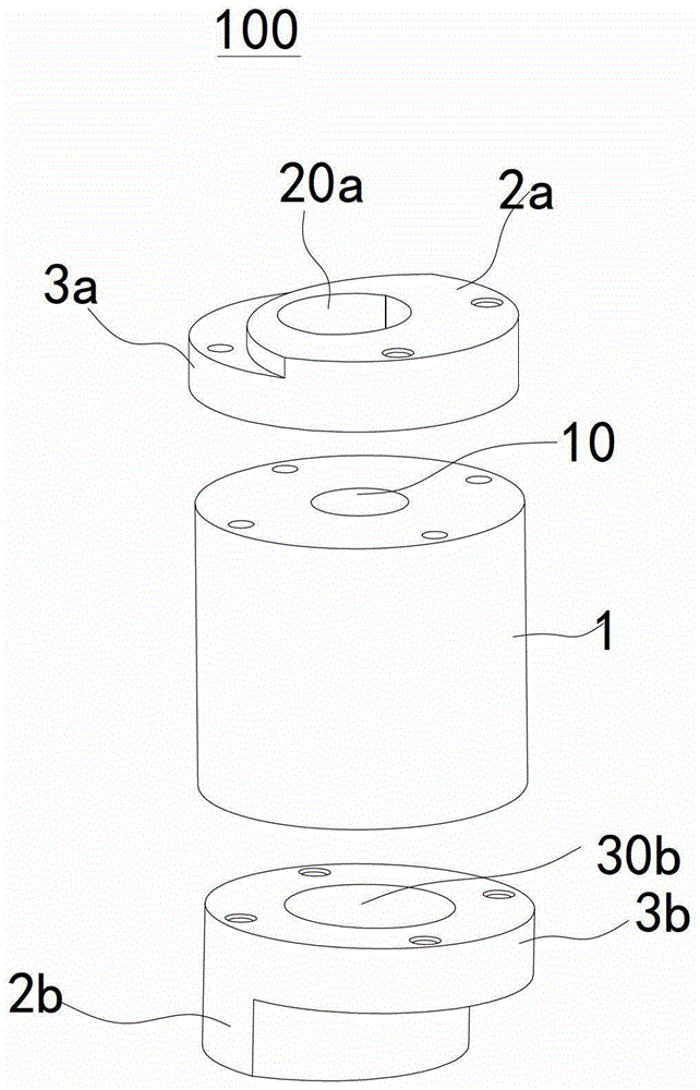
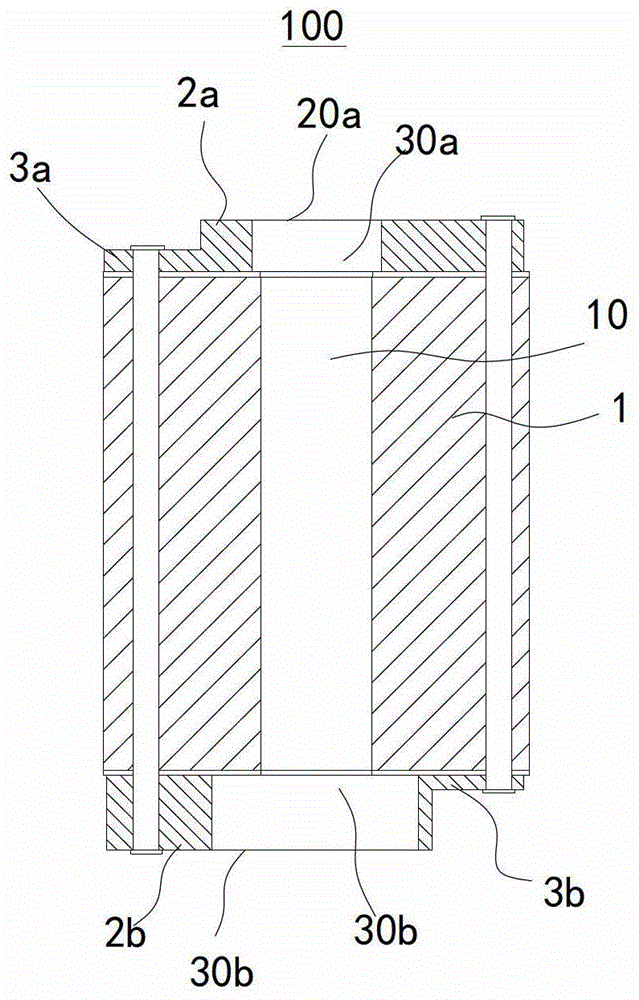
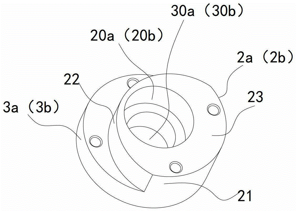
[0050] Embodiments of the present invention are described in detail below, examples of which are shown in the drawings, wherein the same or similar reference numerals designate the same or similar elements or elements having the same or similar functions throughout. The embodiments described below by referring to the figures are exemplary only for explaining the present invention and should not be construed as limiting the present invention.

[0051] In describing the present invention, it is to be understood that the terms "central", "longitudinal", "transverse", "upper", "lower", "top", "bottom", "inner", "outer" etc. indicate The orientation or positional relationship is based on the orientation or positional relationship shown in the drawings, and is only for the convenience of describing the present invention and simplifying the description, rather than indicating or implying that the referred device or element must have a specific orientation or be configured in a specifi...


PUM


Abstract

The invention discloses a rotary compressor and a rotor assembly thereof. The rotor assembly includes: a rotor with a shaft hole; an upper balance weight and a lower balance weight respectively arranged on the top and bottom of the rotor, and the upper balance weight and the lower balance weight respectively have shaft holes coaxial with the shaft hole; The first circular hole and the second circular hole, wherein each of the upper balance weight and the lower balance weight includes: an outer cylinder; an inner cylinder, the inner cylinder intersects the outer cylinder and is connected to the outer cylinder The protruding direction is opposite; the upper end surface, the upper end surface is set on the top of the outer cylinder and the inner cylinder; the lower end surface, the lower end surface is set on the bottom of the outer cylinder and the inner cylinder. According to the rotor assembly of the present invention, when used in a rotary compressor, it can reduce the rotational speed fluctuation of the rotary compressor to reduce vibration and noise, and effectively reduce the fluid noise inside the shell of the rotary compressor and improve its mechanical efficiency. Moreover, the production process is simple and the reliability is high.

Description

technical field [0001] The invention relates to the field of rotary compressors, in particular to a rotor assembly of a rotary compressor and a rotary compressor with the same. Background technique [0002] In the compression structure of the existing rotary compressor, in order to balance the eccentric part of the crankshaft in the pump body and the unbalance generated when the piston rotates with the compressor, semi-annular balance weights are generally installed at both ends of the rotor to reduce compression. The purpose of machine vibration and noise. [0003] In the existing rotary compressors, the common method to reduce the vibration of the compressor and reduce the noise of the compressor is to install a balance weight with a suitable quality at the corresponding position of the two ends of the rotor according to the eccentric part of the crankshaft and the unbalance of the piston. As the mass increases, its volume will also increase accordingly. With the high-spe...

Claims


Application Information

Patent Timeline
Patent Type & Authority Patents(China)
IPC IPC(8): F04C29/00
Inventor 张杰吴多更张奎
Owner GUANGDONG MEIZHI PRECISION MFG
Why Eureka
Try Eureka