Machinery mechanism for achieving lifting and rotating actions

A mechanical mechanism, lifting and rotating technology, applied in mechanical equipment, lifting devices, transmission devices, etc., can solve the problems of complex transmission scheme, low reliability and low precision, and achieve the effect of compact structure, easy manufacture and high precision

Active Publication Date: 2014-01-22
段沧桑
View PDF6 Cites 12 Cited by
  • Summary
  • Abstract
  • Description
  • Claims
  • Application Information

AI Technical Summary

Problems solved by technology

[0004] Through research, it is found that the current mechanical device that realizes the action of rising-forward rotation-reverse rotation-...

Method used


Image

  • Machinery mechanism for achieving lifting and rotating actions
  • Machinery mechanism for achieving lifting and rotating actions
  • Machinery mechanism for achieving lifting and rotating actions

Examples


Embodiment Construction

[0018] The present invention proposes a mechanical mechanism that realizes lifting and rotating actions, and is detailed in conjunction with accompanying drawings 1(a), 1(b), 2(a), 2(b), 3(a), 3(b) and embodiments described as follows:

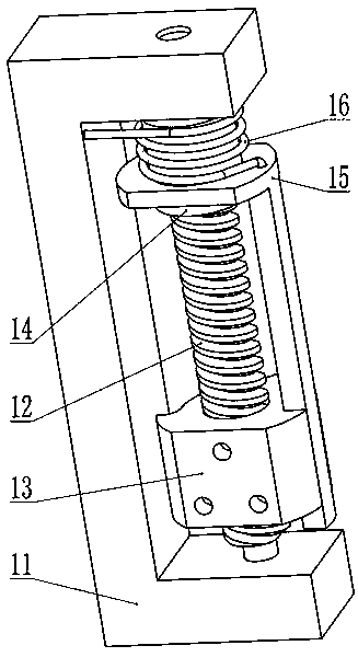
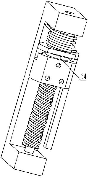
[0019] As shown in Figures 1(a) and 1(b), it is a mechanical mechanism for realizing the lifting and rotating action of the present invention, which includes a base 11, a screw rod 12, a screw sleeve 13, a screw sleeve retaining ring 14, and a screw sleeve rotation Frame 15, torsion spring 16. The mechanism consists of four kinematic pairs, the first is the rotary pair connected between the base 11 and the screw 12, the second is the screw pair connected between the screw 12 and the screw sleeve 13, and the third is the The mobile pair that is connected between screw sleeve 13 and screw sleeve rotary frame 15, the 4th is the rotary pair that is connected between screw rod 12 and screw sleeve rotary frame 15. The screw 12 is installed on the...


PUM


Abstract

The invention relates to a machinery mechanism for achieving lifting and rotating actions. The machinery mechanism comprises a base, a screw rod, a screw sleeve, a screw sleeve check ring, a screw sleeve rotation frame and a torsion spring, and one end of the screw rod and one end of the torsion spring are installed on the base. The machinery mechanism has horizontal motion and rotation functions, wherein the horizontal motion function can achieve the purpose that the screw sleeve is lifted in a horizontal movement mode, the rotation function can achieve the purpose of rotation of the screw sleeve, and the actions of the two functions happen sequentially. The machinery mechanism has the advantages that the structure is compact, rigidity and precision are high, modularization can be achieved easily, complete mechanical coupling is adopted, and the reliability is extremely high. The machinery mechanism adapts to high-temperature, low-temperature, high-electromagnetism, dust and corrosive gas environments, and the machinery mechanism belongs to a kind of solution for replacing multi-power-source associated equipment and replacing single repeated action executing.

Description

technical field [0001] The invention belongs to the field of design and manufacture of transmission equipment, and in particular relates to a high-mechanical coupling mechanism with a single power source and capable of completing lifting-forward rotation-reverse rotation-downward action. [0002] Background technique [0003] With the advancement of science and technology, various industries that previously required manpower are constantly changing to automated production methods. [0004] Through research, it is found that the current mechanical device that realizes the action of rising-forward rotation-reverse rotation-down has problems such as low precision, too complicated electrical, hydraulic and pneumatic transmission schemes, low reliability, and high prices. [0005] Contents of the invention [0006] In order to solve the above-mentioned problems, the present invention designs a single-power high-mechanical coupling mechanical mechanism to perform the mechanica...

Claims


Application Information

Patent Timeline
IPC IPC(8): F16H37/12B66F13/00
CPCB66F3/08B66F3/46F16H25/2015F16H25/2018F16H37/02F16H2025/204F16H2025/2046
Inventor 段沧桑
Owner 段沧桑
Why Eureka
Try Eureka