Morphology compensation type double-optical-axis linear displacement laser interferometer calibration method and device

A laser interferometer, laser interference technology, applied in the direction of using optical devices, measuring devices, instruments, etc., can solve the problem of inconsistent influence, large Abbe error, and inability to determine whether the interferometric mirror group and measuring mirror belong to standard laser interferometer components or It belongs to the problem of being calibrated, and achieves the effect of ensuring accuracy and small Abbe error.

Active Publication Date: 2014-01-22
HARBIN INST OF TECH
View PDF2 Cites 13 Cited by
  • Summary
  • Abstract
  • Description
  • Claims
  • Application Information

AI Technical Summary

Problems solved by technology

Since the two sets of laser interferometers are placed in parallel, the two paths of light are similarly affected by the environment, and the refractive index of air has little influence on the two paths of light. Big error
[0004] figure 2 It is a schematic diagram of the face-to-face laser interferometer calibration device. The standard measuring mirror and the calibrated measuring mirror are installed on the moving platform face to face. The advantage is that the measuring beam axes of the two sets of laser interferometers can be adjusted to almost the same measuring axis. The Abbe error is very small. The disadvantage is that the near end of one interferometer is the far end of the other.
[0005] In 2011, the National Institute of Metrology established the first 80-meter long-length laser interferometer measurement device in China (Leng Yuguo, Tao Lei, Xu Jian. Analysis of the accuracy and influencing factors of the dual-frequency laser interferometer system based on the 80-meter measurement device. Metrology and Testing Technology, 2011, 38(9): 47-49), the standard device used is to place three Agilent5530 long-distance dual-frequency laser interferometers in parallel to form a three-way laser interferometer, and the calibrated laser interferometer The instrument is placed between them for calibration and calibration. This scheme is a derivative of the parallel calibration method, and since three-way light is used for simultaneous measurement, it can compensate for the Abbe error during measurement. However, since three lasers are placed in parallel Therefore, the spatial position of the three-way standard measurement light is relatively far away, and the distance between the measurement light of the calibrated laser interferometer and each standard measurement light is also relatively long. All measurement light paths are affected by the environment differently, and the air refractive index has inconsistent effects on all measurement light paths. , resulting in inaccurate calibration measurements
Since the two sets of laser interferometers share one interferometer group and measuring mirror, it is impossible to determine whether the shared interferometer group and measuring mirror belong to the standard laser interferometer part or the calibrated standard laser interferometer part. Therefore, it is not exactly two sets Calibration of the laser interferometer for calibration

Method used


Image

  • Morphology compensation type double-optical-axis linear displacement laser interferometer calibration method and device
  • Morphology compensation type double-optical-axis linear displacement laser interferometer calibration method and device
  • Morphology compensation type double-optical-axis linear displacement laser interferometer calibration method and device

Examples


Embodiment Construction

[0027] The specific embodiments of the present invention will be further described in detail below in conjunction with the accompanying drawings.

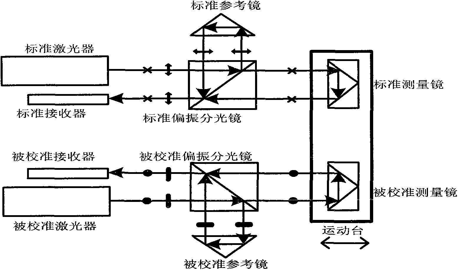
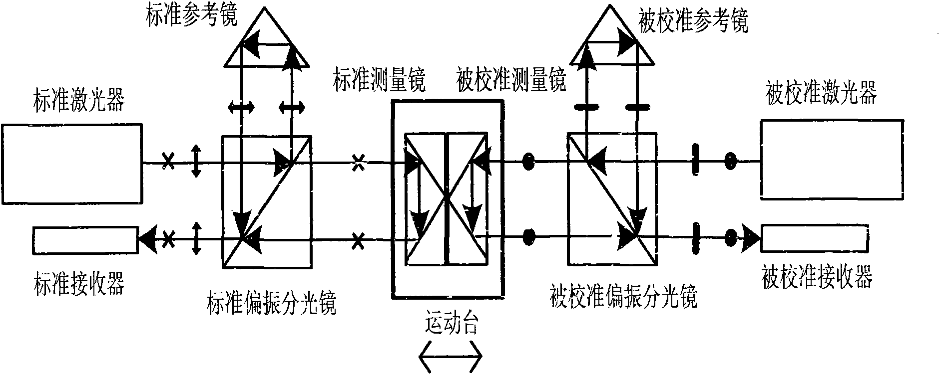
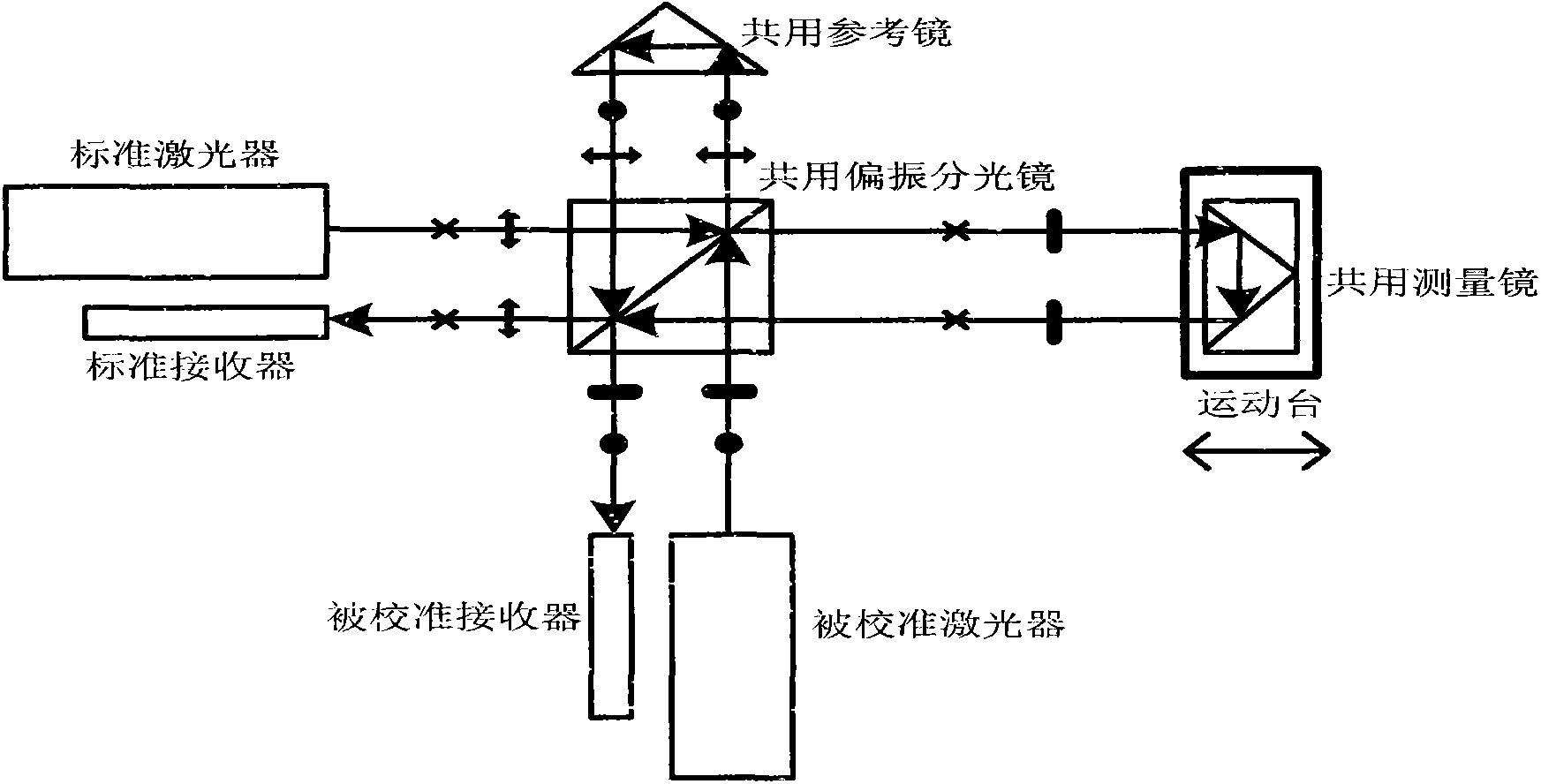
[0028] A shape-compensated dual optical axis displacement laser interferometer calibration device, including a standard laser interferometer laser 1 and two receivers 6, 7 arranged at positions that can receive the interference signal of the standard laser interferometer, the wire connects the two receivers The devices 6 and 7 are respectively connected to the signal processing system 8 of the standard laser interferometer; the output optical path of the standard laser interferometer laser 1 is equipped with an intermediate through hole 12, which allows the calibrated laser interferometer measurement beam 11 to pass through the biaxial hollow standard Laser interference mirror group 2; guide rail 17 is arranged on one side of biaxial hollow standard laser interference mirror group 2, and the moving table 16 is fitted on the guiding ...


PUM


Abstract

The invention discloses a morphology compensation type double-optical-axis linear displacement laser interferometer calibration method and device, and belongs to the technical field of laser measurement. A calibrated laser interferometer measurement light beam is caused to pass through a middle through hole of a double-axis hollow laser interferoscope group and is arranged on the center position of two parallel standard measurement light beams in parallel; in a plane vertical to the two standard measurement light beams, the difference of the environment interference degree between the two standard measurement light beams and the calibrated laser interferometer measurement light beam is small in a line segment area formed by the two standard measurement light beams in the plane projection points; the air refractive index average value of the two standard measurement light beams is approximate to the air refractive index value of the calibrated laser interferometer measurement light beam; a measurement error caused by the surface morphology of a target reflecting mirror reflecting surface is compensated into a linear displacement measurement result to guarantee the accuracy of a linear displacement measurement value.

Description

technical field [0001] The invention belongs to the technical field of laser measurement, and mainly relates to a laser interferometer calibration method and device. Background technique [0002] Laser interferometry linear displacement technology is a standard measurement technology with high precision. It is widely used in precision and ultra-precision machining, microelectronics equipment, nanotechnology industrial equipment and national defense equipment. In order to ensure the accuracy of laser interferometer measurement of linear displacement , requires a scientific and effective linear displacement laser interferometer calibration method and device. The general idea of ​​calibrating a linear displacement laser interferometer is to use a linear displacement laser interferometer with a higher level of precision for calibration. When the accuracy of the two is similar, it is called comparison. In the actual calibration work, most of the linear displacement laser interfe...

Claims


Application Information

Patent Timeline
IPC IPC(8): G01B9/02G01B11/02
Inventor 胡鹏程谭久彬
Owner HARBIN INST OF TECH
Why Eureka
Try Eureka