Preparation method and device of natural gas hydrate with uniform high saturability in sediment
A technology for preparing equipment and sediments, which is applied in the field of preparation of uniform and high-saturation natural gas hydrate, can solve the problems of the influence of experimental simulation results of natural gas hydrate production, and the occurrence state of hydrate is not truly reflected, and achieves a wide range of pressure resistance options. , the effect of reducing high pressure requirements and reducing manufacturing costs
- Summary
- Abstract
- Description
- Claims
- Application Information
AI Technical Summary
Problems solved by technology
Method used
Image

Examples
Embodiment 1
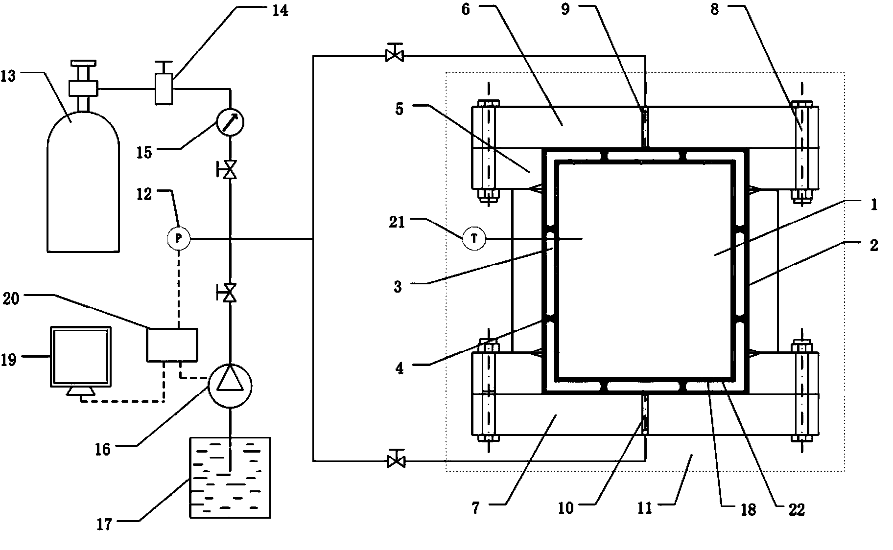
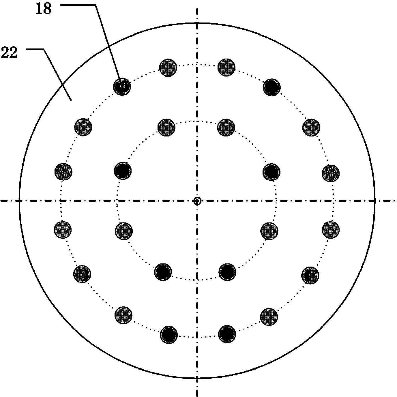
[0027] see figure 1 with figure 2 As shown, a device for preparing natural gas hydrate with uniform high saturation in sediments, including a high-pressure reactor, and a stabilized gas supply module for adjusting and controlling the gas content in the high-pressure reactor, for real-time adjustment and control of system pressure and the supplementary constant pressure liquid supply module of the solution, which is used to provide the constant temperature water bath module of the constant temperature environment for the high pressure reactor. The control module is used to collect the sediment porosity, target three-phase saturation, target generation pressure and temperature data acquisition and processing module of high-pressure reactor, constant-pressure gas supply module, constant-pressure liquid supply module, constant-temperature water bath module, high-pressure The reactor is composed of an inner reactor 1 and an outer reactor 2. The inner reactor 1 is connected with a...
PUM
 Abstract
Description
Claims
Application Information
 - R&D
- Intellectual Property
- Life Sciences
- Materials
- Tech Scout
- Unparalleled Data Quality
- Higher Quality Content
- 60% Fewer Hallucinations
Browse by: Latest US Patents, China's latest patents, Technical Efficacy Thesaurus, Application Domain, Technology Topic, Popular Technical Reports.
© 2025 PatSnap. All rights reserved.Legal|Privacy policy|Modern Slavery Act Transparency Statement|Sitemap|About US| Contact US: help@patsnap.com