
Rapid double power supply switch device and working method thereof

A technology of dual power switching and switching devices, which is applied in the direction of circuit devices, emergency power supply arrangements, power network operating system integration, etc., can solve problems such as power loss, contact arcing, uncontrollable semi-controlled switches, etc., to achieve extended use Ideal effects for life, improved switching speed, rapidity and transient characteristics

Inactive Publication Date: 2014-01-22
STATE GRID CORP OF CHINA +2
View PDF4 Cites 16 Cited by
  • Summary
  • Abstract
  • Description
  • Claims
  • Application Information

AI Technical Summary

Problems solved by technology

[0005] The present invention provides a fast dual-power switch device and its working method, which can effectively solve the inherent problems of traditional mechanical switches such as contact arcing and power loss, as well as the uncontrollable problem of semi-controlled switches, and greatly improve the switching speed and switching efficiency. Long service life, meeting the stringent requirements of sensitive and critical loads on power supply reliability and power quality

Method used


Image

  • Rapid double power supply switch device and working method thereof
  • Rapid double power supply switch device and working method thereof

Examples


Embodiment Construction

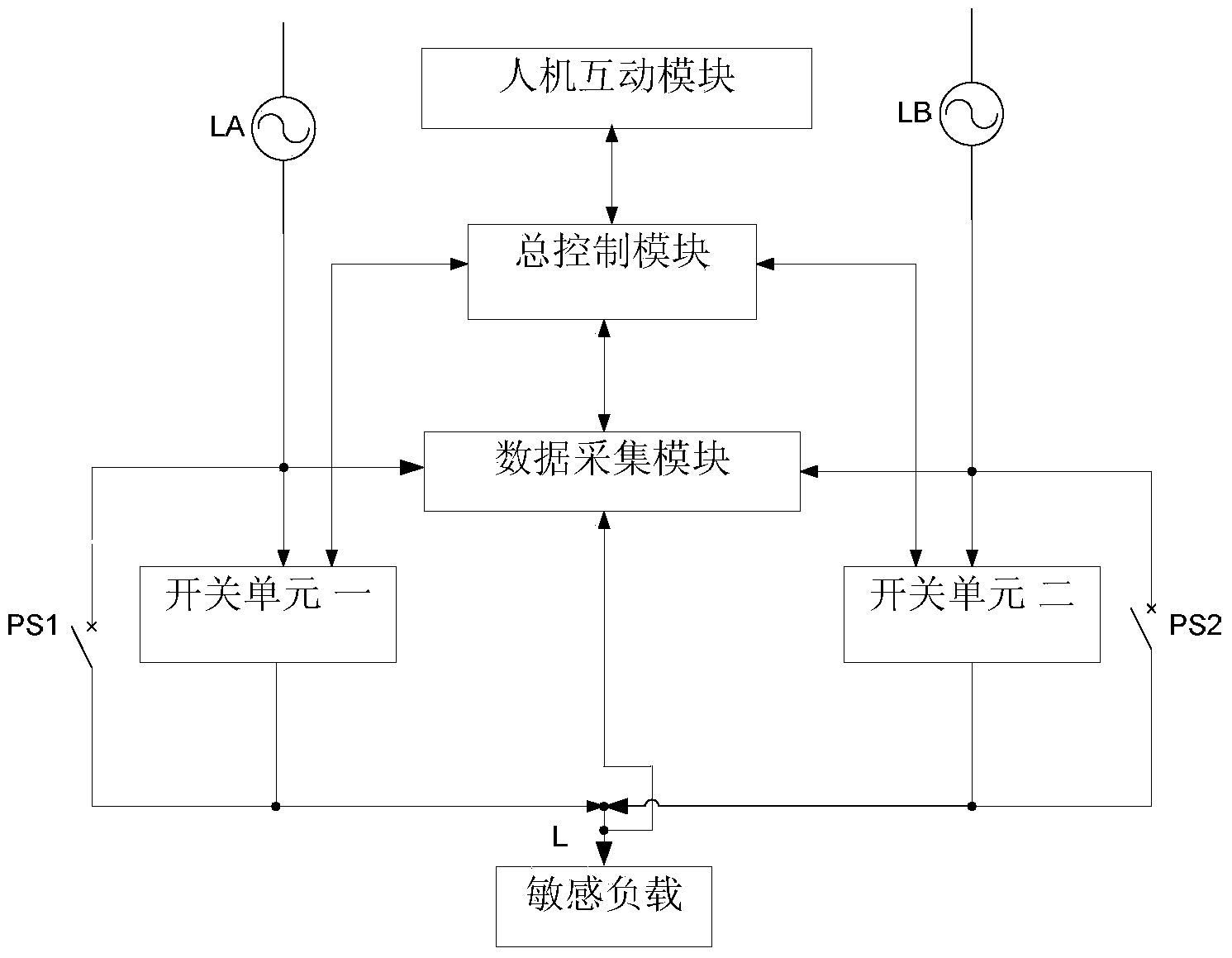
[0029] The present invention as figure 1 , 2 Shown: including normal power supply LA, standby power supply LB, load L, circuit breaker one PS1 and circuit breaker two PS2; said circuit breaker one PS1 is set between said normal power supply LA and load L, said circuit breaker two PA2 Set between the backup power supply LB and the load L;

[0030] It also includes switch unit 1, switch unit 2, data acquisition module and general control module;

[0031] The switch unit one is connected in parallel with the circuit breaker one PS1;

[0032] The switch unit 2 is connected in parallel with the circuit breaker 2 PS2;

[0033] The common power supply LA, the backup power supply LB, and the load L are respectively connected to the input terminals of the data acquisition module, and the data acquisition module also has a communication connection with the total control module;

[0034] The control signal output end of the master control module is connected with the control poles of...


PUM


Abstract

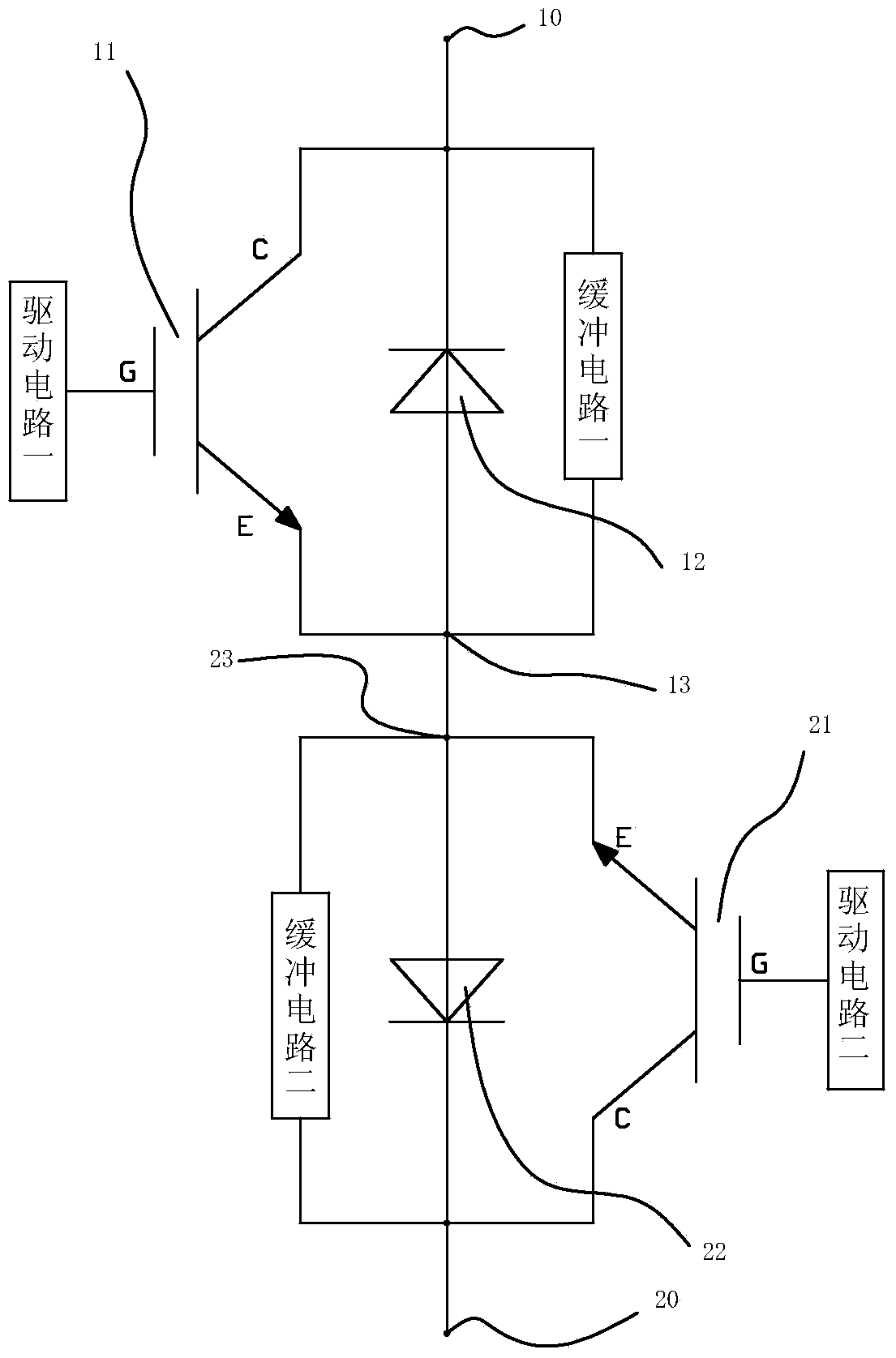
The invention provides a rapid double power supply switch device and a working method thereof, relates to a switch used for guaranteeing power supply continuity and the working method, and can effectively solve the problems of contact arcing, electrical energy loss and the like of a conventional switch. The device comprises a frequently-used power supply, a reserve power supply, a load, a circuit breaker I, a circuit breaker II as well as a switch unit I, a switch unit II, a data acquisition module and a total control module, wherein the structure of the switch unit I or the switch unit II comprises a full control type switching element insulated gate bipolar transistor I, a full control type switching element insulated gate bipolar transistor II, an uncontrollable semiconductor device diode I, an uncontrollable semiconductor device diode II, a buffer circuit I, a buffer circuit II, a drive circuit I and a drive circuit II. Serious affects of the problems such as temporary reduction of power supply voltage, short-term voltage interruption and the like on the load are reduced, and safe and stable operation of a power supply system is guaranteed. According to the rapid double power supply switch device and the working method thereof, power supply switch time reaches a millisecond level, seamless switching can be realized, both the rapidity and the transient characteristic are ideal, and strict requirements of a sensitive and critical load on the power supply reliability and electric energy quality are really met.

Description

technical field [0001] The invention relates to a fast dual power supply switch for ensuring continuity of power supply and a working method thereof. Background technique [0002] In the current power supply system, the power supply network sometimes has problems such as large-scale impact or nonlinear load switching, lightning strikes, load failures, etc., resulting in a sag in the power supply voltage or short-term power supply interruptions, which will lead to problems such as computer Some equipment of servers and data processors that are not allowed to be powered off has power supply termination, which will bring serious consequences to a large number of continuous production industries, financial centers, data centers, hospitals, transportation and other systems, resulting in immeasurable economic losses losses and even casualties. In view of this, industries with special requirements for power supply are often equipped with backup power supply. [0003] In the ca...

Claims


Application Information

Patent Timeline
Patent Type & Authority Applications(China)
IPC IPC(8): H02J9/04
CPCY02B70/30Y04S20/20
Inventor 陆圣芝金丽莉黄俊王宝安苗振林谭风雷
Owner STATE GRID CORP OF CHINA
Learn More