Light module power supply control method and system

A technology for power control and optical modules, which is applied to non-electrical signal transmission systems, signal transmission systems, electrical components, etc. It can solve the problem that the power supply of optical modules is not isolated, it is difficult to control the power supply of optical modules, and it is easily affected by voltage fluctuations, etc. To achieve the effect of saving energy consumption, convenient and reasonable control, and reducing risks

Active Publication Date: 2014-01-22
PHICOMM (SHANGHAI) CO LTD
View PDF5 Cites 10 Cited by
  • Summary
  • Abstract
  • Description
  • Claims
  • Application Information

AI Technical Summary

Problems solved by technology

[0023] In view of the above-mentioned shortcomings of the prior art, the purpose of the present invention is to provide a method and system for controlling the power supply of the optical module, which is used to solve the problem that the power supply part of the optical module in the prior art is not isolated, is easily affected by voltage fluctuations, and operates It is not easy to control the power supply of the optical module, which will cause unnecessary energy loss on the optical module

Method used


Image

  • Light module power supply control method and system
  • Light module power supply control method and system
  • Light module power supply control method and system

Examples


Embodiment 1

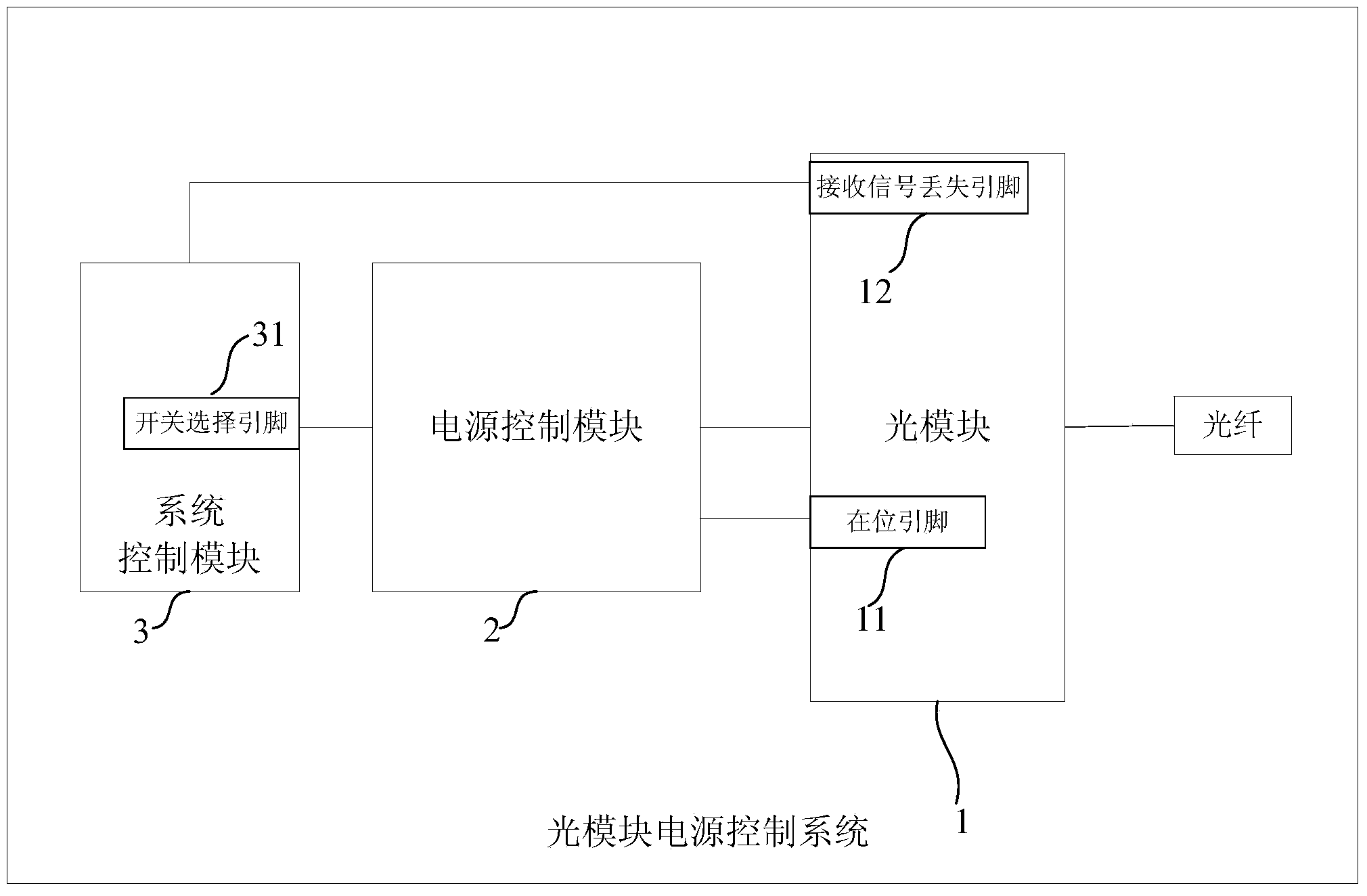
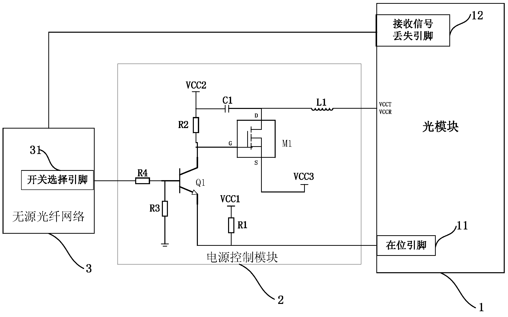
[0051] This embodiment provides an optical module power control system, which is used to control the signal transmission of the optical fiber. Please refer to figure 1 , which is a schematic structural diagram of the optical module power control system of the present invention. As shown in the figure, the optical module power control system controls the opening and closing of the optical module by adding a power switch control module to the power supply part of the optical module. The optical module power control system includes: an optical module 1 , a power control module 2 , and a system control module 3 .

[0052] Each component of the optical module power control system will be described separately below.

[0053] Optical module 1 is connected with optical fiber, is used for converting electric signal into optical signal, and judges the insertion state of described optical module 1 according to the level input to the position pin on optical module 1; Described optical mo...

Embodiment 2

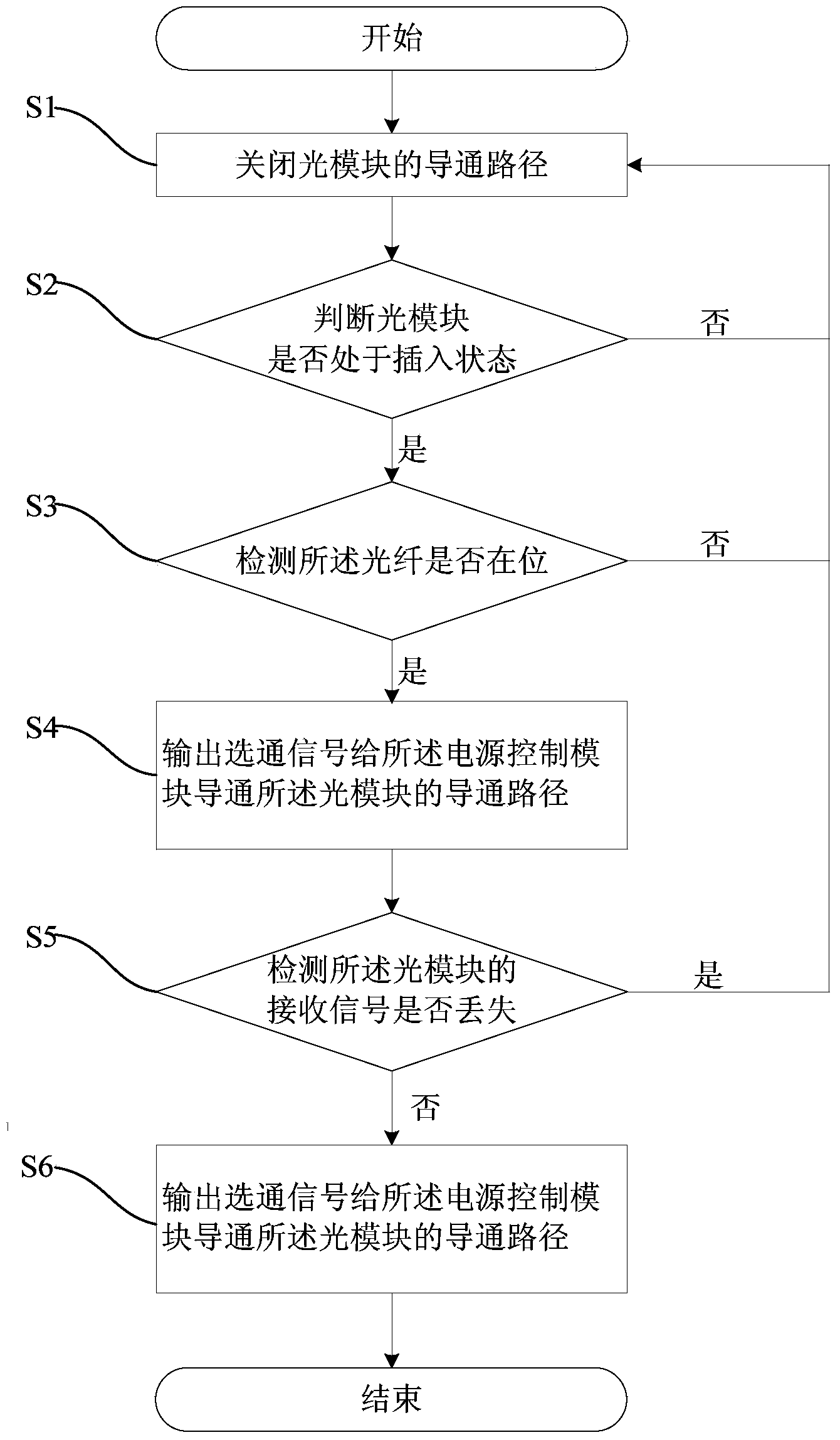
[0065] This embodiment provides an optical module power control method, which is applied to an optical module power control system including an optical module, a power control module, and a system control module to control signal transmission of optical fibers. The optical module power control method includes:


PUM


Abstract

The invention provides a light module power supply control method, which is applied to a light module power supply control system consisting of a light module, a power supply control module and a system control module for controlling optical fibers. The method comprises the steps that the plugging state of the light module is detected, and if the light module is not plugged, forbidden signals are output for closing a conducting path of the light module; if the light module is plugged, whether the optical fibers are in position or not is detected, if the optical fibers are in position, gating signals are output to the power supply control module for conducting the conducting path of the light module; if the optical fibers are not in position, the forbidden signals are output for closing the conducting path of the light module; whether receiving signals of the light module are lost or not is detected, if the receiving signals of the light module are lost, the forbidden signals are output for closing the conducting path of the light module; if the receiving signals of the light module are not lost, the gating signals are output to the power supply control module for conducting the conducting path of the light source module. The light module power supply control method has the advantages that safety and reliability are realized during the plugging and the unplugging of the light module, the control is more convenient and reasonable, the damage to the light module is avoided, the existence of risk during the hot plugging and unplugging is reduced, and the energy consumption of the light module in the non-working state is reduced.

Description

technical field [0001] The invention belongs to the field of optical fiber communication, and relates to a power control method and system, in particular to an optical module power control method and system. Background technique [0002] In the process of optical fiber transmission from the optical line terminal (OLT) equipment to the user, the optical module plays a very important role, because the optical module realizes the photoelectric conversion between the equipment and the optical fiber. The optical module is a precise device, and the increase in bandwidth also makes the usage of the optical module very large, resulting in energy consumption. The incorrect use of large-scale optical modules is also a great waste of energy. If the power supply of the optical module is connected to the power supply of the whole board, the stability of the optical module will be affected. Using a reasonable and correct method can reduce this waste and at the same time Control and manag...

Claims


Application Information

Patent Timeline
Patent Type & Authority Applications(China)
IPC IPC(8): H03K19/094G08C23/06
Inventor 张贵清
Owner PHICOMM (SHANGHAI) CO LTD
Why Eureka
Try Eureka