
HUD comprising holographic optical elements

A holographic optical element and technology of optical elements, applied in the field of display devices, can solve the problems of relatively sensitive visibility, correlation, expensive computing power, etc.

Inactive Publication Date: 2014-01-22
ROBERT BOSCH GMBH
View PDF8 Cites 17 Cited by
  • Summary
  • Abstract
  • Description
  • Claims
  • Application Information

AI Technical Summary

Problems solved by technology

A disadvantage of this system however is that the visibility of the displayed information is relatively sensitively line-of-sight dependent due to the strong angular dependence of the diffraction image
Another disadvantage of this technique is the relatively high and thus expensive computing power required to convert conventional image data into interference patterns for the control

Method used


Image

  • HUD comprising holographic optical elements
  • HUD comprising holographic optical elements
  • HUD comprising holographic optical elements

Examples


Embodiment Construction

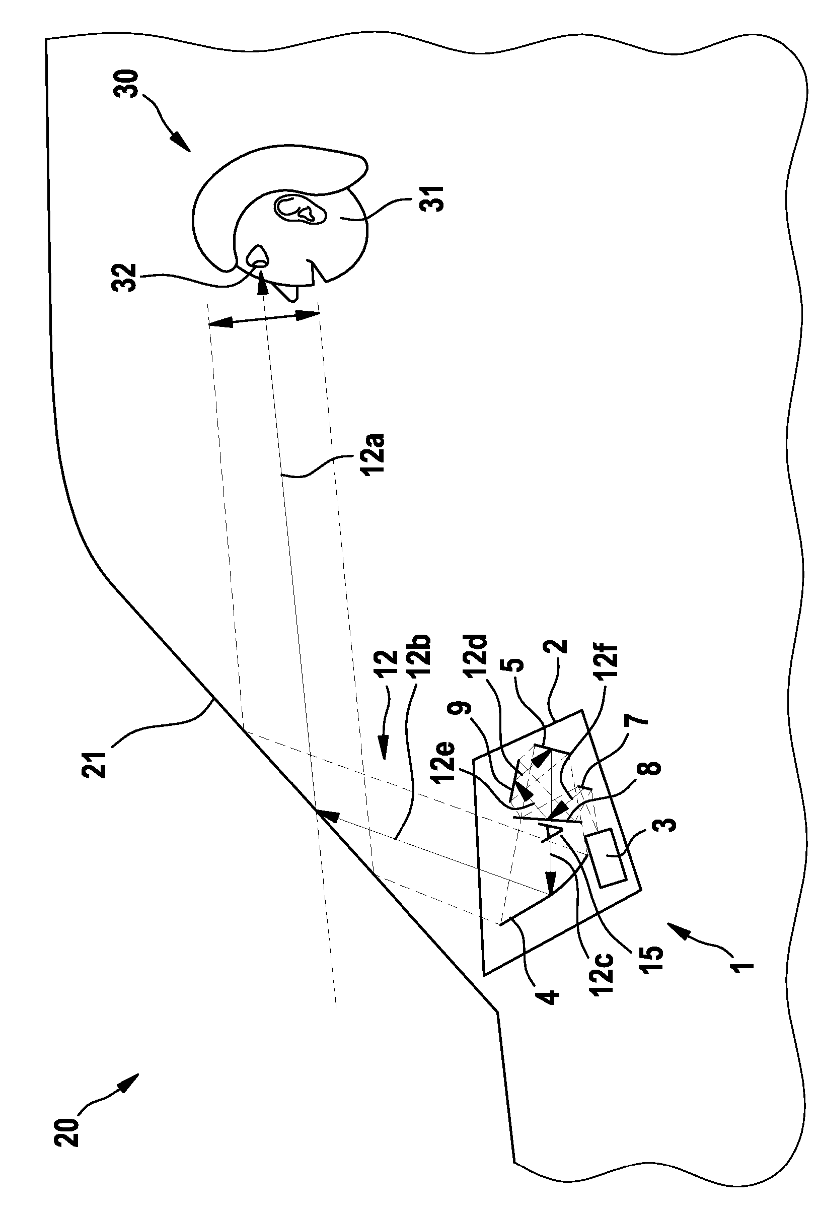
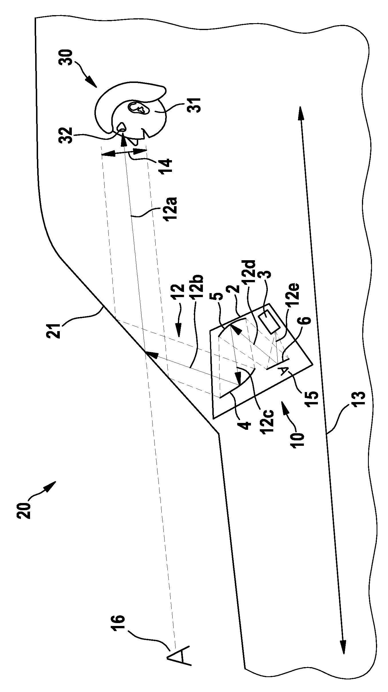
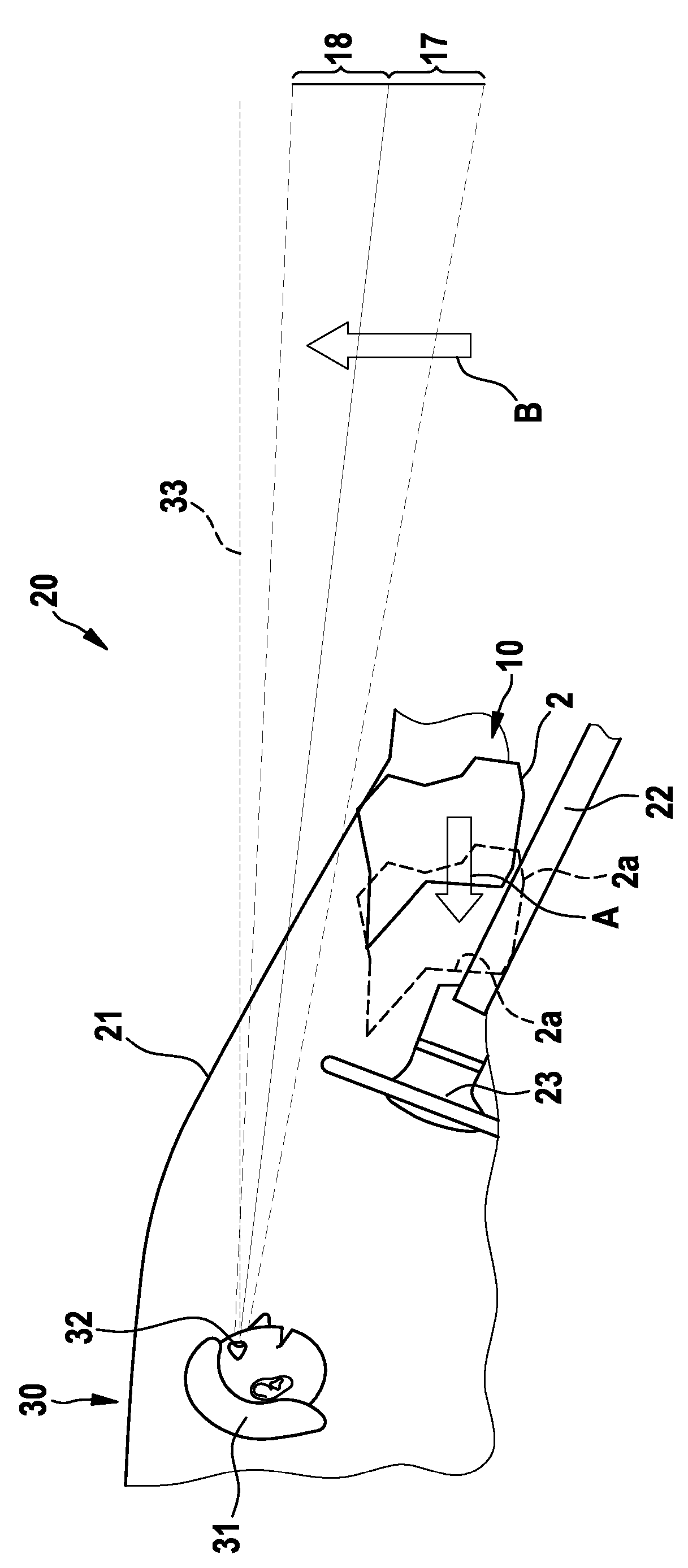
[0036] FIGS. 1 a and 1 b each show a motor vehicle 20 with a head-up display 10 according to the prior art, which can display information to a driver 30 when viewed in the direction of travel. The driver 30 is symbolically represented in all FIGS. 1 a , 1 b , 2 and 3 by a head 31 with eyes 32 .

[0037] Figures 1a and 1b show the configuration of the head-up display 10 in a motor vehicle 20, which is similarly applicable to the figure 2 with 3 HUD 1 shown in .

[0038] The head-up display 10 is accommodated in the motor vehicle 20 below the lower region of the windshield pane 21 shown. When looking through the windscreen 21 , the driver 30 sees a segment 12a of the light path 12 into which the projector 3 of the head-up display 10 can send light beams to display images. Only when the eyes 32 of the driver 30 are located in the vertical area 14 is the driver 30 able to perceive the virtual image 16 of the displayed information at the virtual image distance 13 . Because the ...


PUM


Abstract

A display device (1), more particularly a head-up display, comprising a light-emitting image source (3) and comprising optical elements (4, 5, 6, 7, 8, 9) forming a beam path (12) for beams is presented. In this case, the optical elements (4, 5, 6, 7, 8, 9) comprise a holographic optical element (8) having a predefined optical imaging function and a reflector (5). The holographic optical element (8) is positioned in a manner spatially separated from the reflector (5) in the beam path (12). Moreover, the holographic optical element (8) is arranged in the beam path (12) in such a way that beams in a first section of the beam path are directed onto the holographic optical element (8) in order to deflect them under the influence of the imaging function of the holographic optical element (8) into a second section of the beam path in a new direction. The reflector (5) and the holographic optical element (8) are arranged relative to one another in such a way that beams emitted by the reflector (5) into a third section of the beam path (12) can at least partly transilluminate the holographic optical element, wherein illumination angles of transilluminating beams in the third section of the beam path (12) substantially deviate from angles of incidence at which an influence of the imaging function of the holographic optical element (8) is effective.

Description

technical field [0001] The invention relates to a display device according to the preamble of claim 1 . Background technique [0002] Thanks to advances in optical technology, it is possible to build smaller and more energy-efficient optical systems, which are increasingly used in display systems in automobiles. This especially facilitates the development of head-up displays, with which vehicle data such as speed, rotational speed, fuel level or weather conditions, for example, can be displayed in the driver's field of vision depending on the traffic situation in the direction of travel. Therefore many new display device solutions and improvements have been disclosed in the last few years. [0003] Holographic optical elements are disclosed in Physical and Technical Optical Systems [1]. A known application of holographic optical elements in display systems is, for example, to correct imaging errors of optical paths or individual optical elements. For example DE 103 44 688...

Claims


Application Information

Patent Timeline
IPC IPC(8): G02B27/01
CPCG02B27/0103G02B2027/0123G02B2027/015
Inventor J.魏因加滕
Owner ROBERT BOSCH GMBH
Learn More