Method for prolonging service life of face milling cutter based on heat pipe phase changes

An end mill and heat pipe technology, applied in the field of mechanical processing, can solve problems such as patents that have not yet been seen, and achieve the effects of reducing manufacturing costs, cutting temperatures, and low prices

Inactive Publication Date: 2014-01-29
ANHUI AGRICULTURAL UNIVERSITY
View PDF2 Cites 43 Cited by
  • Summary
  • Abstract
  • Description
  • Claims
  • Application Information

AI Technical Summary

Problems solved by technology

At present, heat pipe technology has been applied to a certain extent in the fields o...

Method used


Image

  • Method for prolonging service life of face milling cutter based on heat pipe phase changes
  • Method for prolonging service life of face milling cutter based on heat pipe phase changes
  • Method for prolonging service life of face milling cutter based on heat pipe phase changes

Examples


Embodiment 1

[0041] Such as Figure 2a-Figure 2c As shown, the schematic diagram of the temperature change of the end mill cutting edge with time under different conditions of use, where: the specification of the end mill used in the experimental measurement is Side cutting amount a c Take 14mm.

[0042] Figure 2a Indicates: when no cutting fluid and heat pipe 1 are used, the schematic diagram of the change of the machining temperature of the cutting edge of the end mill with time; Figure 2b Indicates: when cutting fluid is used, the schematic diagram of the temperature change of the cutting edge of the end mill with time; Figure 2c Indicates: when heat pipe 1 is used, the schematic diagram of the change of machining temperature of end mill cutting edge with time.

[0043] The measurement results show that: under the same processing conditions, the cutting temperature of the end mill using the heat pipe 1 is lower than that of the cutting fluid.

[0044] Since the three-sided edge ...

Embodiment 2

[0047] Such as Figure 3a-Figure 3c As shown, the wear condition of the outer tip of the main cutting edge measured by the end mill after processing several grooves under different conditions of use, where: the specification of the end mill used in the experimental measurement is Side cutting amount a c Take 28mm; Figure 3a Indicates: when cutting fluid and heat pipe 1 are not used, the wear condition of the outer tip of the main cutting edge measured by the end mill after machining 1490 grooves; Figure 3b Indicates: when cutting fluid is used, the wear condition of the outer tip of the main cutting edge measured by the end mill after machining 1751 grooves; Figure 3c Indicates: When heat pipe 1 is used, the wear condition of the outer tip of the main cutting edge is measured after the end mill has processed 2000 grooves.

[0048] The measurement results show that under the same processing conditions, the flank wear of the end mill using heat pipe 1 is lighter than that...

Embodiment 3

[0051] Such as Figure 4 As shown, the schematic diagram of the service life of the end mill under different conditions of use, where: the specification of the end mill used in the experimental measurement is Side cutting amount a c Take 50mm; SD means: without using cutting fluid and heat pipe 1; CF means: using cutting fluid; HF means: using heat pipe 1. The subscripts 1 and 2 respectively indicate the number of end mills under different cooling conditions.

[0052] The measurement results show that: under the same processing conditions, the life of the end mill using the heat pipe 1 is longer than that of the end mill using cutting fluid.

[0053] In addition, the cutting fluid used in this experiment is the cutting oil commonly used in the manufacturing industry.


PUM


Abstract

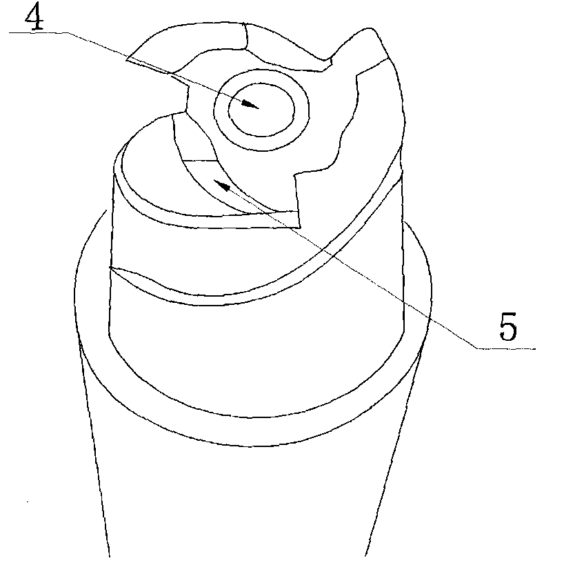
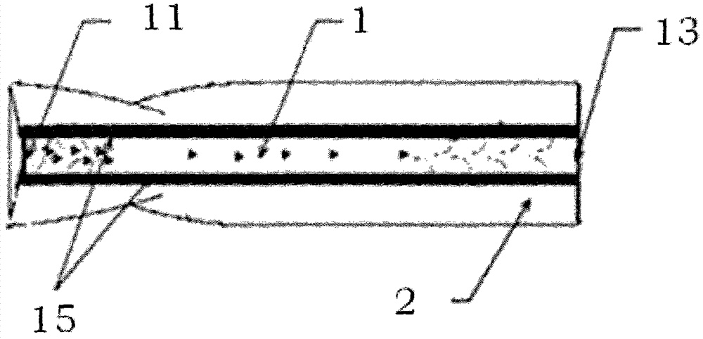
The invention provides an environment-friendly method for prolonging the service life of a face milling cutter based on heat pipe phase changes, so durability of the face milling cutter can be remarkably improved under a milling especial for high-speed milling machining condition. The method comprises a novel face milling cutter. The novel face milling cutter comprises a heat pipe, a face milling cutter shank, a face milling cutter body and a face milling head. The face milling head is arranged at one end of the face milling cutter body, the face milling cutter shank is arranged at the other end of the face milling cutter body, the heat pipe is implanted into the face milling cutter body from the face milling cutter shank in the direction parallel with the axis of the face milling cutter body and is close to the main cutting edge part on the face milling head, and the heat pipe is filled with a liquid absorption core. Heat pipe phase change heat transferring is adopted in the method, so the heat pipe is higher than cutting fluid in heat transfer efficiency. A heat pipe technology is adopted, the cutting temperature of the face milling cutter is lowered, the heat pipe is more environment-friendly than the cutting fluid, and personal injuries to operation staff do not exist. In addition, the heat pipe adopted in the method is cheaper than the cutting fluid in market price, and therefore manufacturing cost of products of enterprises can be reduced.

Description

technical field [0001] The invention relates to the field of mechanical processing, in particular to a method for improving the service life of an end mill based on the phase transition of a heat pipe. Background technique [0002] In the machining industry, cutting heat has always been a problem that people generally care about, and it is also a key technology that enterprises need to solve urgently. Cutting process produces a lot of cutting heat, and a large amount of cutting heat is transmitted to the tool, resulting in an increase in the temperature of the cutting part of the tool. Excessively high cutting temperature will accelerate tool wear, such as diffusion wear, adhesive wear and chemical wear, thereby reducing tool durability and prompting early tool failure. [0003] Milling is interrupted cutting. During the milling process, because the total area of ​​the cutting layer is constantly changing, the milling force fluctuates greatly. When milling, especially in ...

Claims


Application Information

Patent Timeline
IPC IPC(8): B23Q11/10B23C5/06
CPCB23C5/06B23C5/28
Inventor 朱林尹成龙任天健程曦彭双双方梁菲
Owner ANHUI AGRICULTURAL UNIVERSITY
Why Eureka
Try Eureka