Folding telescopic cantilever beam system of walking bridge erecting machine with lower guide beam

A technology of cantilever beams and bridge erecting machines, applied in bridges, bridge construction, erection/assembly of bridges, etc., can solve the problems of unusable lifting equipment, inability to extend into tunnels, low strength of cantilever beams, etc., to reduce human participation , saving manpower and reducing construction costs

Active Publication Date: 2015-09-30
HEBEI UNIV OF TECH
View PDF5 Cites 0 Cited by
  • Summary
  • Abstract
  • Description
  • Claims
  • Application Information

AI Technical Summary

Problems solved by technology

When erecting the last hole before Suiqian, because the cantilever beam of the bridge erecting machine is too high to extend into the tunnel, it is often necessary to use lifting equipment to remove the fixed cantilever beam, but due to the construction site at the tunnel entrance Lifting equipment is sometimes even unusable, and even if lifting equipment can be used for disassembly, the construction period will be longer
[0004] In order to overcome the above-mentioned problems, some people have developed the upward folding cantilever beam and the folding cantilever beam bridge erecting machine, but these cantilever beams have the disadvantages of low strength and inconvenient operation.

Method used


Image

  • Folding telescopic cantilever beam system of walking bridge erecting machine with lower guide beam
  • Folding telescopic cantilever beam system of walking bridge erecting machine with lower guide beam
  • Folding telescopic cantilever beam system of walking bridge erecting machine with lower guide beam

Examples


Embodiment Construction

[0023] The present invention will be further described below in conjunction with specific embodiments and accompanying drawings. The specific embodiments are only used to further describe the present invention in detail, and do not limit the protection scope of the claims of the present invention.

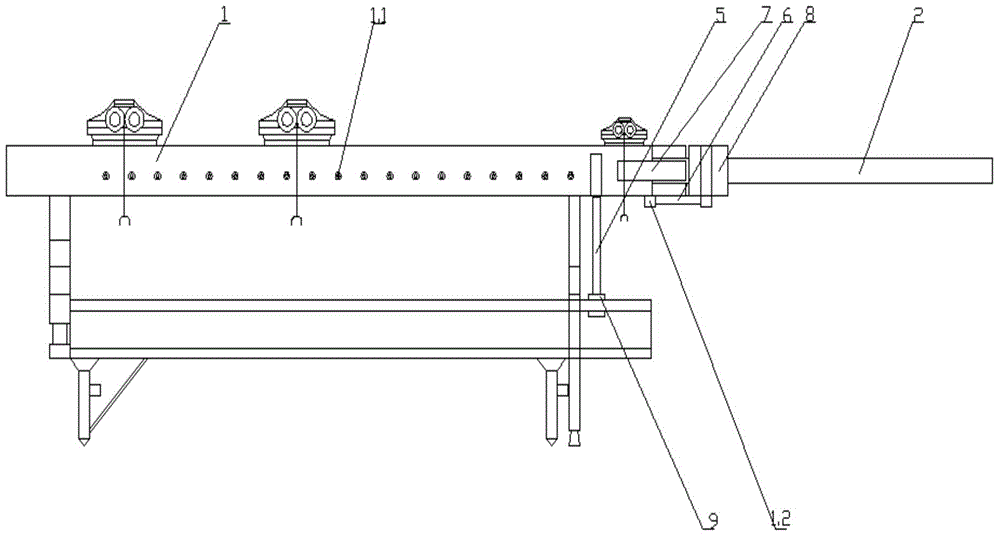
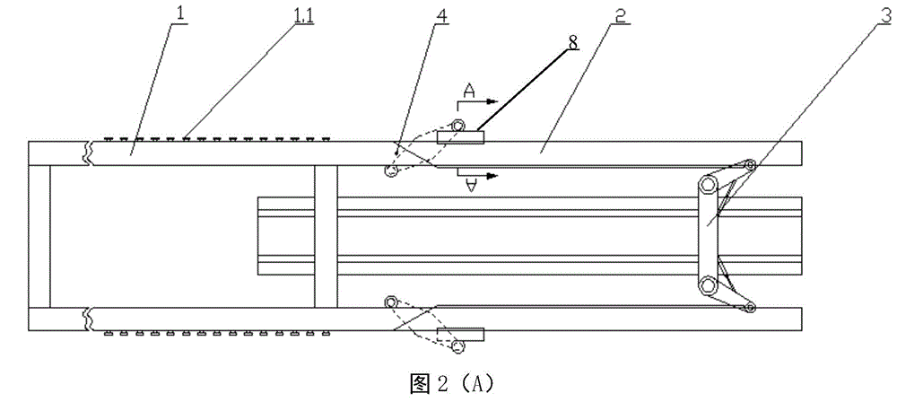
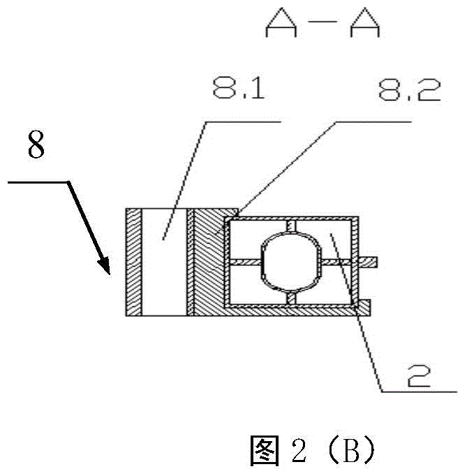
[0024] The lower guide beam walking type bridge erecting machine designed by the present invention can turn and stretch the cantilever beam system (system for short, see Figure 1-7 ) includes a main beam 1, a cantilever beam 2, a cantilever beam beam 3, a positioning pin 4, an auxiliary leg 5 of a bridge erecting machine, a connecting rod 6, a connecting plate 7, a connecting sleeve 8 and a traveling motor 9; the main beam 1 and The cantilever beam 2 is connected together through the connecting rod 6, the connecting plate 7 or the connecting sleeve 8; the positioning pin 4 is located on the lower side of the main beam, and the cantilever beam 3 is located on the cantilever beam 2; ...


PUM


Abstract

The invention discloses a bending retractable cantilever system of a lower guide girder crawler-type bridge erecting machine. The bending retractable cantilever system comprises a main girder, cantilevers, a cantilever beam, positioning pins, bridge erecting machine supports, a connecting rod, a connecting board and a walking driver. The main girder and the cantilevers are connected together through the connecting rod and the connecting board or a connecting sleeve; the positioning pins are arranged on the lower portion of the main girder, the cantilever beam is disposed on the cantilevers; the bridge erecting machine supports are arranged under the main girder and drivingly connected with the walking motor. According to the lower guide girder crawler-type bridge erecting machine with the bending retractable cantilever system, the retraction process of the cantilever beam does not require long-distance upward or outward bending of the cantilever beam and just needs to integrally retract backwards; during the retraction process of the cantilever beam, the auxiliary supports can support the cantilever beam to move towards the main girder, so that backward retraction of the cantilever beam during a large-cantilever process can be avoided and the security coefficient is relatively high.

Description

technical field [0001] The invention relates to bridge erecting equipment, in particular to a folding and telescopic cantilever beam system of a walking bridge erecting machine with a lower guide beam, which is suitable for erecting high-speed railway bridges and the like. Background technique [0002] In the past ten years, with the rapid development of my country's railway passenger dedicated line and high-speed railway construction, various types of bridge erecting machines have been put into use, and most of these bridge erecting machines adopt the walking structure of the lower guide beam, and the cantilever There are some problems when the lower guide beam walking bridge erecting machine of the beam erects the front and end holes of the tunnel. [0003] According to the railway network plan formulated by our country in 2008, high-speed or express railway networks should also be developed in the southwestern mountainous area. According to statistics, the proportion of b...

Claims


Application Information

Patent Timeline
Patent Type & Authority Patents(China)
IPC IPC(8): E01D21/10
Inventor 陈子顺孙琪于菲张建辉丁大龙温琳韩波杨洪超
Owner HEBEI UNIV OF TECH
Why Eureka
Try Eureka