Multi-frequency-band array antenna compact in structure

An array antenna and compact structure technology, applied in the field of communication, can solve the problems that it is difficult to meet the application requirements of 700MHz LTE, it is difficult to expand the 700MHz frequency band, and the dual-frequency antenna has a large windward area, so as to reduce operation and maintenance costs, reduce the number of antennas, and have a compact structure Effect

Active Publication Date: 2014-01-29
GUANGDONG BROADRADIO COMM TECH
View PDF7 Cites 27 Cited by
  • Summary
  • Abstract
  • Description
  • Claims
  • Application Information

AI Technical Summary

Problems solved by technology

However, in order to weaken the coupling between high and low frequency radiating elements, the distance between them should not be too small, resulting in a large windward area of ​​the dual-frequency antenna
[0005] In addition, most of the antennas in the prior art work in the 790-960MHz and 1710-2690MHz frequency bands, it is difficult to extend to the 700MHz frequency band, and it is difficult to meet the application requirements of 700MHz LTE
Moreover, the existing mosaic structure is suitable for a row of high-frequency radiation units and a row of low-frequency radiation units. If it is necessary to add a row of high-frequency radiation units, the antenna width must be increased, which limits its application.

Method used


Image

  • Multi-frequency-band array antenna compact in structure
  • Multi-frequency-band array antenna compact in structure
  • Multi-frequency-band array antenna compact in structure

Examples


Embodiment 1

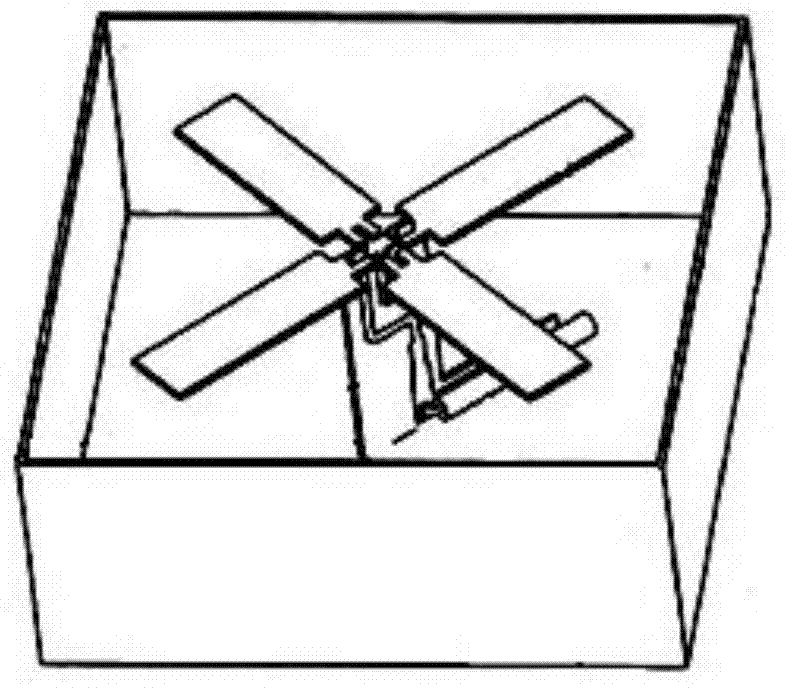
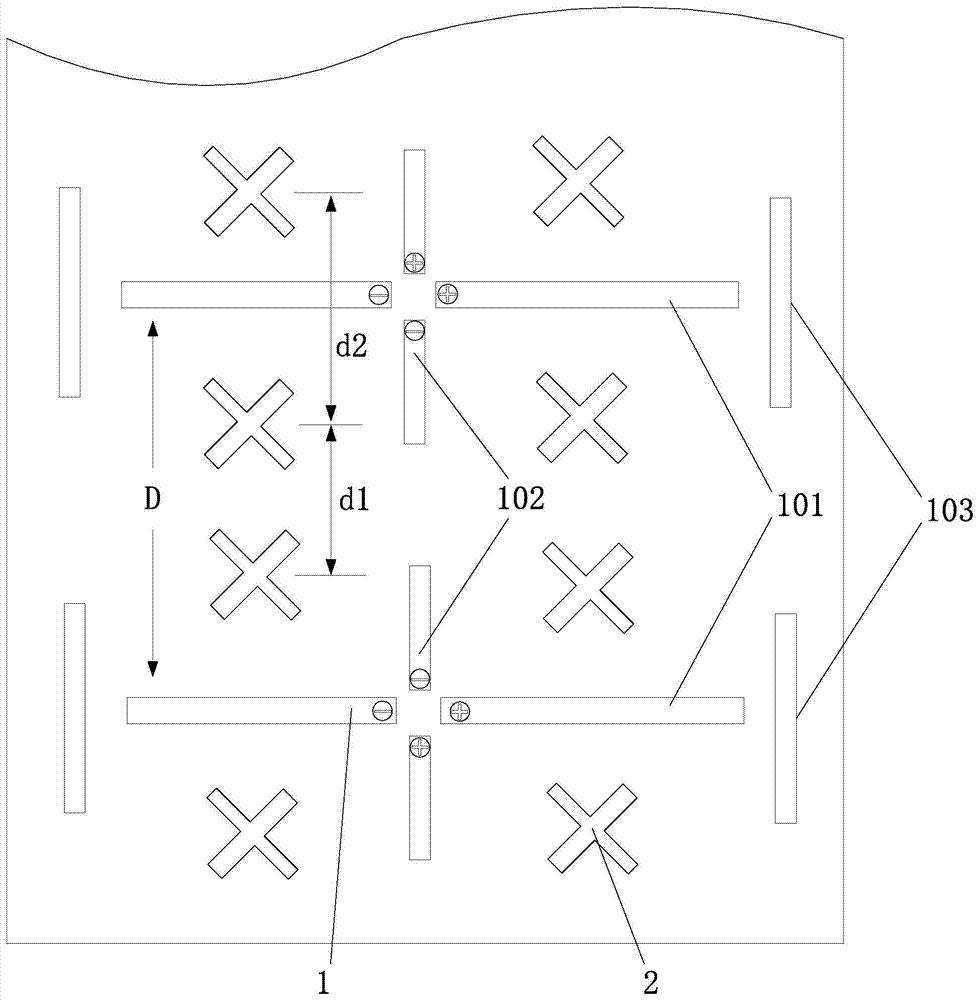
[0034] Such as Figure 2 to Figure 4 As shown, a compact 3-band array antenna provided by the embodiment of the present invention includes a metal reflector, and a low-frequency radiation unit 1 working in a lower frequency band and a high-frequency radiation unit 1 working in a higher frequency band installed on the metal reflector. Frequency radiation unit 2. Preferably, the low-frequency radiation unit 1 works in the frequency range of 698-960 MHz, and the high-frequency radiation unit 2 works in the frequency range of 1710-2690 MHz.

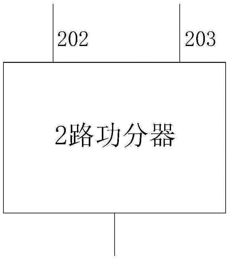
[0035] The low-frequency radiating unit 1 includes horizontal oscillators 101 and vertical oscillators 102 that are orthogonal to each other. The horizontal oscillators 101 and vertical oscillators 102 are connected to a power divider feeding network to generate a ±45-degree polarized far-field radiation pattern. A plurality of low-frequency radiation units 1 are arranged at equal intervals along the first reference line to form a low-freque...

Embodiment 2

[0049] Such as Figure 5 As shown, the embodiment of the present invention is changed on the basis of the first embodiment, and a 5-band array antenna is provided. Specifically, the multiple high-frequency radiation units 2 in each high-frequency array in the embodiment of the present invention belong to two mutually independent high-frequency systems. In other words, there are four mutually independent high-frequency systems in the embodiment of the present invention, which are respectively Figure 5 The part selected by the four rectangular frames in , together with another low-frequency system, constitutes a 5-band array antenna in which one low-frequency system and four high-frequency systems coexist.

[0050] Other features in this embodiment of the present invention are the same as those in Embodiment 1, so they will not be repeated here.

Embodiment 3

[0052] Such as Image 6 As shown, the embodiment of the present invention provides a 4-band antenna including a TD intelligent system. Among them, the four high-frequency arrays selected in the figure are TD intelligent systems that work in the 1880-2690MHz frequency band and cover the working frequency bands of TD-SCDMA and TD-LTE, that is, the four high-frequency arrays belong to the same high-frequency system . The two high-frequency arrays located on both sides of the TD intelligent system belong to two independent high-frequency systems and work in the 1710-2690MHz frequency band; the low-frequency array in the center of the entire array antenna belongs to the 698-960MHz frequency band low frequency system.

[0053] Other features in this embodiment of the present invention are the same as those in Embodiment 1, so they will not be repeated here.

[0054] It should be pointed out that in the three embodiments provided above, the number of high-frequency radiation units...


PUM


Abstract

The invention relates to a multi-frequency-band array antenna compact in structure. The multi-frequency-band array antenna comprises a metal reflective board, a low-frequency radiation unit working in low frequency bands and a high-frequency radiation unit working in high frequency bands, and the low-frequency radiation unit and the high-frequency radiation unit are arranged on the metal reflective board. The low-frequency radiation unit and the high-frequency radiation unit are arranged on the metal reflective board in a nested mode, and the orthographic projection of the low-frequency radiation unit and the orthographic projection of the high-frequency radiation unit do not coincide. The low-frequency radiation unit is formed by connecting a horizontal vibrator and a vertical vibrator with a power divider feed network and is flexible in structure, and a distance and other parameters can be flexibly configured according to practical application requirements. Due to the adoption of the structure, circuit network losses are few, the radiation characteristic stability of the multi-frequency-band array antenna within an ultra wide band range can be maintained, 2G, 3G and 4G LTE systems in mobile communication are compatible, the number of antennas used in a base station can be reduced, station distribution cost can be lowered, and operation and maintenance cost can also be lowered.

Description

technical field [0001] The invention relates to the communication field, in particular to a multi-band array antenna with compact structure. Background technique [0002] In recent years, the large-scale use of smart mobile terminals represented by smart phones and tablet computers has led to rapid growth of data services in mobile communications. In order to meet the requirements for high-speed data transmission in mobile communications, major operators at home and abroad are vigorously developing the fourth-generation (4G) mobile communication technology mainly based on TD-LTE and FDD-LTE. Today, 2G, 3G and the upcoming 4G LTE network coexist, and multiple systems using different frequency bands exist at the same time, requiring the use of base station antennas that can work in different frequency bands. Using ordinary narrow-band antennas, a base station needs to arrange many sub-antennas, which increases system complexity and property costs. In order to reduce the cost...

Claims


Application Information

Patent Timeline
Patent Type & Authority Applications(China)
IPC IPC(8): H01Q21/00H01Q21/24H01Q21/30H01Q19/10H01Q1/52
Inventor 吴壁群
Owner GUANGDONG BROADRADIO COMM TECH
Why Eureka
Try Eureka