Enterprise power grid optimizing configuration method

A technology for optimizing configuration and power grid, applied in the direction of circuit devices, electrical components, energy industry, etc., to achieve the effect of increasing independence, improving enterprise efficiency, and strong anti-interference ability

Inactive Publication Date: 2014-01-29
苏州华安普电力科技股份有限公司
View PDF5 Cites 2 Cited by
  • Summary
  • Abstract
  • Description
  • Claims
  • Application Information

AI Technical Summary

Problems solved by technology

[0002] The power grid is a circuit network used to connect power sources and electrical equipment. It is mainly composed of wires and various circuit components. Power compensation optimization method, including firstly determining the structure of the distribution network and the actual load conditions, through modeling the structure of the distribution network, such as the connection mode of the line, the number of distribution transformers, the number of reactive power compensation devices before compensation, Position, get the topological structure of the distribution network, input the original data, calculate the parameters before reactive power compensation, aim at the minimum network loss, optimize the reactive power compensation capacity and position of the 10kV distribution network through the genetic algorithm, based on the full Life cycle management selects the optimal calculation of configuration capacity. After the optimization process is completed, the optimization result is output. Through the calculation of the power flow before and after the optimal configuration, the compensation effect is verified, and the plan is adjusted accordingly, which can optimize the reactive power compensation provided by the power supply enterprise. cost, improve the utilization rate of equipment, and improve the economic benefits of power supply enterprises, but this invention cannot solve the problem of how to measure the input power to optimize power distribution, how to disconnect the circuit in time when the current or voltage changes suddenly, and protect the circuit. Safety, how to group the output current, increase the independence of the circuit, reduce the probability of power failure, so as to improve the safety of enterprise power consumption

Method used


Image

  • Enterprise power grid optimizing configuration method

Examples


Embodiment Construction

[0016] In order to make the technical means, creative features, goals and effects achieved by the present invention easy to understand, the present invention will be further described below in conjunction with specific embodiments.

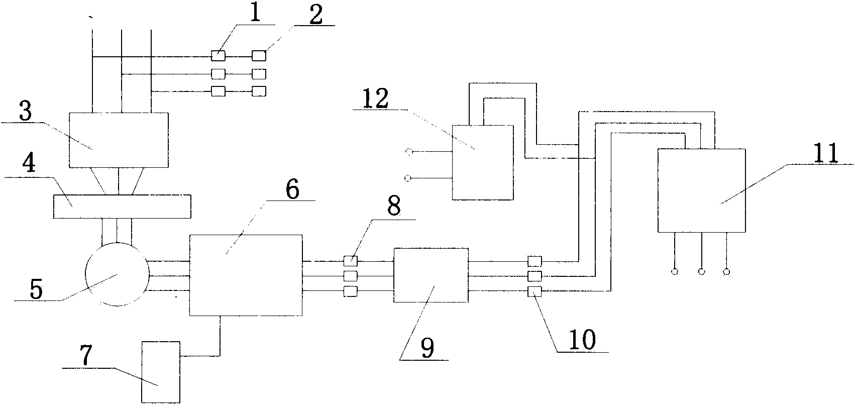
[0017] A method for optimal configuration of an enterprise power grid, the method comprising the following links:

[0018] (1) Power supply input: The three-phase high-voltage wires are first connected to three lightning rods 2 through the circuit breaker 1, so that when the input circuit is struck by lightning, the lightning current has a passage to the ground, which can protect the safety of the circuit, and then it is sent through the protection pipeline The substation room 3 first passes through the three-wire shunt joint 4, then passes through the AC converter 5, and finally sends it to the power supply measurement transformer 6, which can measure the input power, thereby optimizing power distribution, saving resources, reducing energy consump...


PUM


Abstract

The invention discloses an enterprise power grid optimizing configuration method and relates to the field of electrical engineering. The enterprise power grid optimizing configuration method includes the four steps of power input, current metering, power supply for power and power supply for illumination. A three-phase high voltage wire is led to a transformer room through a protective pipeline, and the three-phase high voltage wire passes through a three-wire shunt connector first, then passes through a converter and finally is led to a power supply power measurement transformer. Because the power of an input power supply can be measured, power distribution can be optimized, resources are saved, energy consumption is reduced, enterprise benefits are improved, power supply for power and power supply for illumination are output separately, independence of a circuit is improved, the probability of power failure can be lowered, and electrical safety of an enterprise is improved.

Description

technical field [0001] The invention relates to the field of electrical engineering, in particular to a method for optimal configuration of an enterprise power grid. Background technique [0002] The power grid is a circuit network used to connect power sources and electrical equipment. It is mainly composed of wires and various circuit components. Power compensation optimization method, including firstly determining the structure of the distribution network and the actual load conditions, through modeling the structure of the distribution network, such as the connection mode of the line, the number of distribution transformers, the number of reactive power compensation devices before compensation, Position, get the topological structure of the distribution network, input the original data, calculate the parameters before reactive power compensation, aim at the minimum network loss, optimize the reactive power compensation capacity and position of the 10kV distribution netwo...

Claims


Application Information

Patent Timeline
Patent Type & Authority Applications(China)
IPC IPC(8): H02J3/00
CPCY02P80/10
Inventor 顾华顾魏
Owner 苏州华安普电力科技股份有限公司
Why Eureka
Try Eureka