

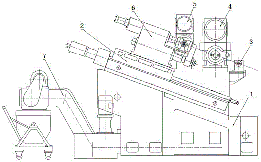
Compound machine tool for milling end face and boring center hole in oblique guide rail
A technology for drilling center holes and compound machine tools, applied in the field of compound machine tools, can solve the problems of affecting processing quality, low degree of automation, low processing efficiency, etc., and achieve the effect of automatic cleaning, high degree of automation, and high processing efficiency
- Summary
- Abstract
- Description
- Claims
- Application Information
AI Technical Summary
Problems solved by technology
Method used
Image

Examples
Embodiment Construction
[0026] Below in conjunction with accompanying drawing and specific embodiment, further illustrate the present invention, should be understood that these embodiments are only for illustrating the present invention and are not intended to limit the scope of the present invention, after having read the present invention, those skilled in the art will understand various aspects of the present invention Modifications in equivalent forms all fall within the scope defined by the appended claims of this application.
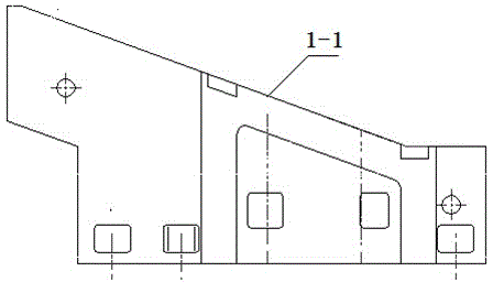
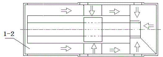
[0027] Such as Figure 1 to Figure 7 As shown, a compound machine tool for milling end faces and drilling center holes with inclined guide rails is characterized in that it comprises: a base (1), a mobile workbench (2) installed on the inclined table (1-1) of the base (1), installed The workpiece positioning device (3), the milling device (4) and the drilling device (5) on the base, the fixture (6) installed on the mobile worktable (2), the cooling and chip removal devic...
PUM
 Abstract
Description
Claims
Application Information