Novel flapping rotary wing structure and corresponding micro-miniature flapping rotary wing device

A fluttering rotor and micro-miniature technology, applied in the field of design and manufacture of micro-miniature aircraft, can solve the problems of conflicting size and payload requirements, low aerodynamic efficiency, etc., and achieve the effects of increasing load, reducing energy consumption, and reducing structural weight

Active Publication Date: 2014-02-05
BEIHANG UNIV
View PDF5 Cites 10 Cited by
  • Summary
  • Abstract
  • Description
  • Claims
  • Application Information

AI Technical Summary

Problems solved by technology

[0009] The purpose of the present invention is to overcome the shortcoming of the low aerodynamic efficiency of the current fluttering rotor structure near the rotating shaft, to solve the contradiction between the size and payload requirements of the micro-aircraft under the existing technical conditions, and to meet the needs of the micro-aircraft with the ability to hover at the same time. ability to fly peacefully

Method used


Image

  • Novel flapping rotary wing structure and corresponding micro-miniature flapping rotary wing device
  • Novel flapping rotary wing structure and corresponding micro-miniature flapping rotary wing device
  • Novel flapping rotary wing structure and corresponding micro-miniature flapping rotary wing device

Examples


Embodiment

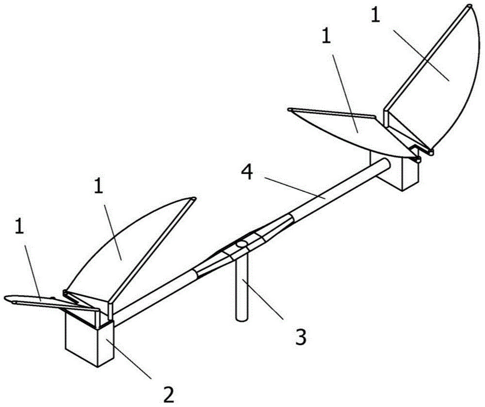
[0035] In this example, a set of parameter sizes in the design steps of the micro-miniature flapping rotor device of the present invention are provided, combined with the above manufacturing steps about the micro-miniature flapping rotor device of the present invention:

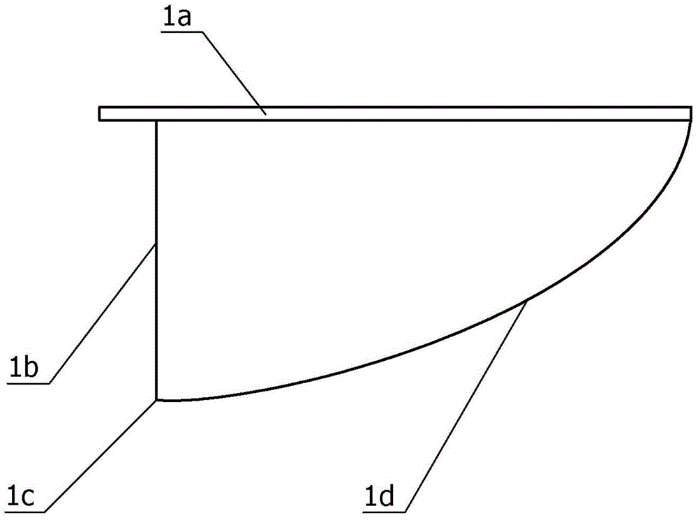
[0036] In the first step, the material of the flapping wing surface is polyvinyl chloride film, the leading edge skeleton is a carbon fiber skeleton with a diameter of 1mm, the span of the single flapping wing is 135mm, the chord 1b is 90mm, and the trailing edge 1d of the flapping wing is in the shape of a parabola , and the trailing edge point 1c is the apex of the parabola, which is used as a single-point fixed point;

[0037] In the second step, a micro motor is used, and the power supply is a lithium battery;

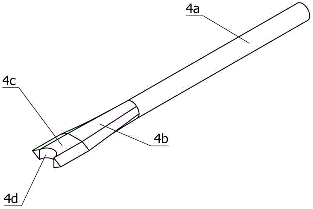
[0038] In the third step, the material of the half beam is carbon fiber, the length of the middle section 4c of the half beam is 45mm, the length of the transition section 4b is 60mm, the connecti...


PUM


Abstract

The invention discloses a novel flapping rotary wing structure and a corresponding micro-miniature flapping rotary wing device. The flapping rotary wing structure is characterized in that two pairs of complete flapping wings are arranged on two ends of a cross beam in a dissymmetry manner, a flex-wing film generates a lifting force and a thrust force simultaneously during an upper-down flapping process of flapping wings, two thrust forces in opposite directions form a force couple to drive the cross beam and the flapping wings to perform self-driven rotation without generating reaction torque. The flapping rotary wing device designed by utilizing the structure comprises the flapping wings, an assembling body provided with a driving mechanism and a power supply, a connecting shaft and half cross beams, wherein the half cross beams are assembled together to form the cross beam, the middle of the cross beam is fixedly connected with one end of the connecting shaft, and the flapping wings are fixed on the assembling body; an axis which is relative to the connecting shaft is installed at the two ends of the cross beam in the dissymmetry manner. The flapping rotary wing structure provided by the invention has the good lifting efficiency, the useful load of an aircraft can be obviously increased, the requirements of hovering and level flight can be simultaneously met, and the application range of a micro-miniature aircraft is effectively widened.

Description

technical field [0001] The invention belongs to the technical field of micro-aircraft design and manufacture, and more specifically relates to a design method and manufacturing technology of a miniature flapping rotor device combining a flapping wing and a rotor. Background technique [0002] Micro air vehicle is a new type of aircraft developed for military purposes in the mid-1990s. In 1992, a research report on future military technology submitted by the US RAND Corporation to the US DARPA (Defense Advanced Research Project Agency) first proposed the concept of micro air vehicles. Compared with conventional unmanned aerial vehicles, micro-miniature aerial vehicles have the advantages of small size, light weight, low-cost flying platform, convenient manipulation, flexible maneuvering, low noise, and good concealment. It has a very broad application prospect, which has attracted widespread attention from all over the world. [0003] Micro-aircraft can be divided into thre...

Claims


Application Information

Patent Timeline
Patent Type & Authority Applications(China)
IPC IPC(8): B64C33/00
Inventor 向锦武孙毅李道春甄冲范新
Owner BEIHANG UNIV
Why Eureka
Try Eureka