
Aerator

An aerator and air bubble technology, applied in the field of aerator, can solve the problems of large exhaust resistance loss, easy blockage of pores, blockage of intake pipe, etc., and achieve the effect of stable operation and obvious non-return effect

Active Publication Date: 2014-02-05
林太才 +1
View PDF6 Cites 20 Cited by
  • Summary
  • Abstract
  • Description
  • Claims
  • Application Information

AI Technical Summary

Problems solved by technology

However, this micro-pore diffusion method has the following problems: 1. The loss of exhaust resistance is large; 2. The pores are easily blocked; 3. There are strict dust removal and filtration requirements for the air source entering the aeration system; Low durability and reliability
[0006] However, through a large number of engineering operation practices, the non-return effect of this kind of aerator has exposed many problems, especially when it is used in the intermittent activated sludge tank, the sludge is always suspended in the water and enters from the rotating impeller blades. There is a lot of muddy water in the intake pipe, so long-term operation will lead to uneven aeration as a whole, and even blockage of the intake pipe, making the aerator run unstable and affecting the operation effect of the aerator

Method used


Image

  • Aerator
  • Aerator
  • Aerator

Examples


Embodiment Construction

[0040] The following are specific embodiments of the present invention and in conjunction with the accompanying drawings, the technical solutions of the present invention are further described, but the present invention is not limited to these embodiments.

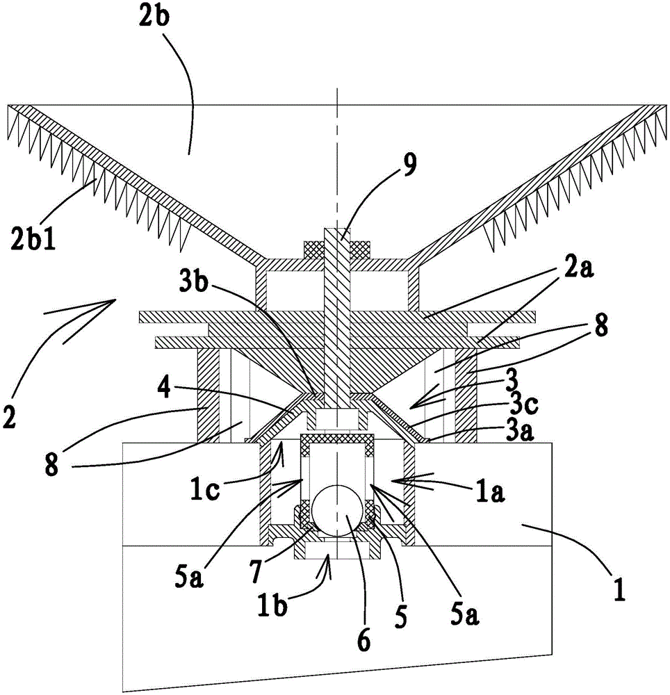
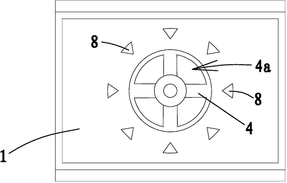
[0041] Such as figure 1 As shown, the aerator includes a mounting base body 1, the middle part of the mounting base body 1 has an air inlet cavity 1a, the upper end of the air intake cavity 1a has an air outlet 1c, and the lower end of the air intake cavity 1a has an air inlet 1b.

[0042] Such as figure 1 with Figure 4 As shown, the air intake cavity 1a is vertically provided with an air intake pipe 5, the air inlet 1b is located at the lower end of the air intake pipe 5, and the air intake pipe 5 is provided with a check ball 6. The upper end of air intake pipe 5 is blocked. Except for the air inlet 1b and the air outlet 1c in the air inlet pipe 5, other parts of the air inlet cavity are sealed from the outside world...


PUM


Abstract

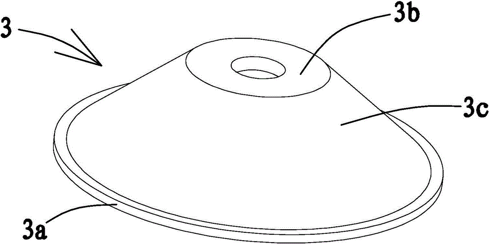
The invention provides an aerator belonging to the technical field of water treatment, and aiming to solve the problem that in the existing aerator, foreign matters get into a pipeline easily and cause unstable operation of the aerator. The aerator provided by the invention comprises a mounting seat, wherein an inlet air cavity is formed in the middle of the mounting seat; an air inlet is formed in the bottom of the inlet air cavity; an air outlet is formed in the top of the inlet air cavity; a cutting component is arranged above the inlet air cavity; a vibrating diaphragm prepared from a rubber material is arranged at the air outlet and comprises a lamellar positioning part and an inclined sealing part; a supporting frame matched with the shape of the lower surface of the vibrating diaphragm is fixedly connected with the air outlet; the vibrating diaphragm is kept close to the upper surface of the supporting frame; on the supporting frame, an exhaust through hole communicated with the inlet air cavity is formed below the sealing part of the vibrating diaphragm; the positioning part of the vibrating diaphragm is fixedly connected to the supporting frame. Because the vibrating diaphragm is arranged at the air outlet to prevent cement from entering an air inlet pipeline, the aerator is relatively stable in operation.

Description

technical field [0001] The invention belongs to the technical field of water treatment and relates to an aerator. Background technique [0002] In the aerobic sewage treatment process, microorganisms are used to decompose organic pollutants in the water body to achieve the purpose of water purification. The biochemical activities of microorganisms must have an oxygen source, and the function of the aerator is to diffuse the air delivered by the blower through the intake pipe into the water body to provide the oxygen source required by the microorganisms. The air bubbles dissolve the oxygen in the air bubbles in the water when they come into contact with the water body. The contact surface between air bubbles and water body is the place where oxygen transfer takes place. The more bubbles produced by the diffusion of gas volume per unit volume, the larger the contact surface between gas and liquid, and the higher the efficiency of oxygen transfer. [0003] At present, micro...

Claims


Application Information

Patent Timeline
IPC IPC(8): C02F3/12
CPCY02W10/10
Inventor 林太才张锡良陈学群
Owner 林太才
Learn More