Viscous material conveying pipe supporting device, supporting structure and concrete conveying machinery

A technology of support device and support structure, which is applied to pipeline supports, mechanical equipment, building structures, etc., and can solve the problems of unsatisfactory flexural rigidity, increased weight, and easy cracking of welds.

Active Publication Date: 2014-02-05
ZOOMLION HEAVY IND CO LTD
View PDF6 Cites 6 Cited by
  • Summary
  • Abstract
  • Description
  • Claims
  • Application Information

AI Technical Summary

Problems solved by technology

[0005] the above figure 1 and figure 2 The disadvantages of the viscous material conveying pipe support device and its supporting structure in the prior art shown are obvious. The deflection stiffness of the support pipe section 2a of the above viscous material support device is basically the same in all directions, which leads to During the process of pipe conveying materials, the fixed pipe section 3a of the viscous material conveying pipe support device is at the position where it is welded to the boom section of the cloth boom. Due to the large impact load of the material pumping, the stress concentration is obvious, and the arm of the boom The welds at joint joints are prone to cracking, which leads to a low service life of the viscous material conveying pipe support device, and even causes viscous material conveying machinery to malfunction, making it impossible to carry out cloth work
In addition, the flexural stiffness of the viscous material conveying pipe support structure around t

Method used


Image

  • Viscous material conveying pipe supporting device, supporting structure and concrete conveying machinery
  • Viscous material conveying pipe supporting device, supporting structure and concrete conveying machinery
  • Viscous material conveying pipe supporting device, supporting structure and concrete conveying machinery

Examples


Embodiment Construction

[0033] The specific embodiments of the present invention will be described in detail below in conjunction with the accompanying drawings. It should be understood that the specific embodiments described here are only used to illustrate and explain the present invention, and the protection scope of the present invention is not limited to the following specific embodiments. .

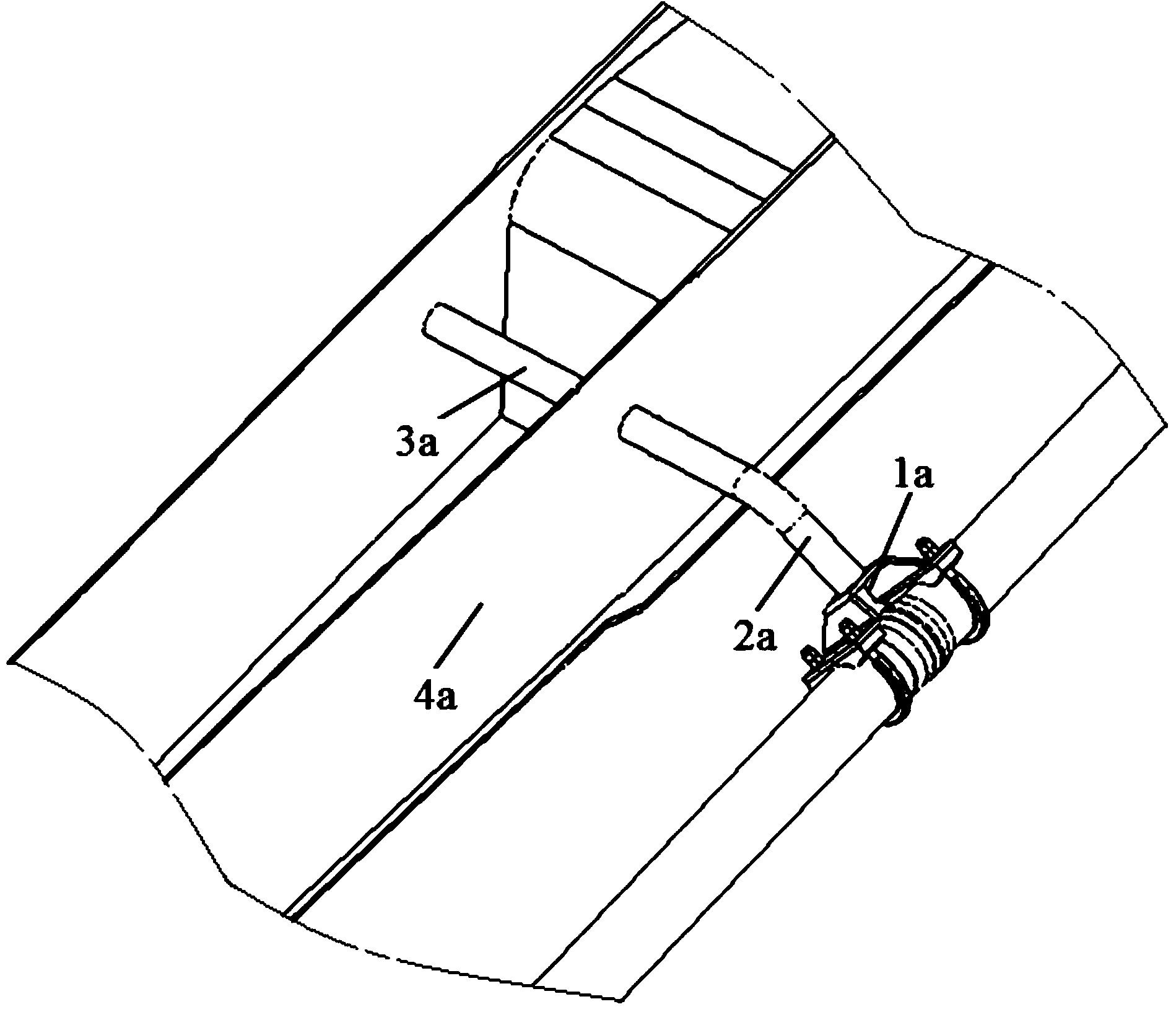
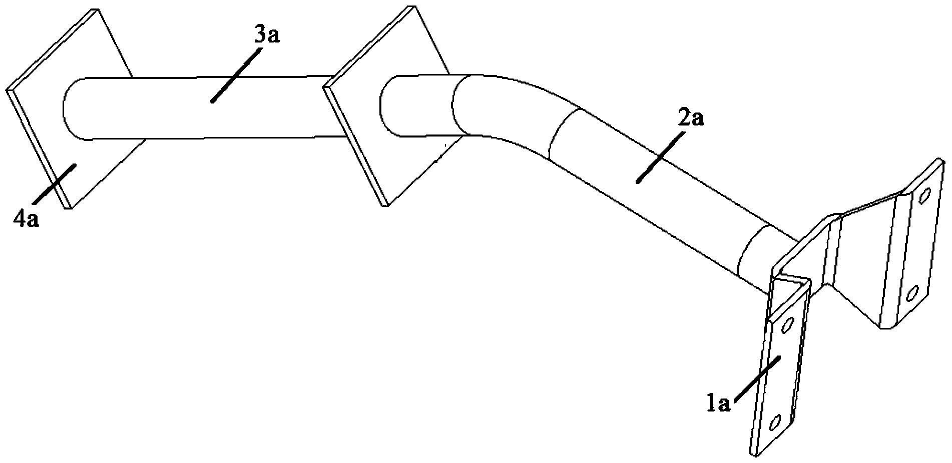
[0034]As mentioned above, the viscous material conveying pipe support structure in the prior art, such as the concrete pipe support structure on the concrete pump truck distribution boom, has a relatively low Large, that is, when a force is applied to the support pipe section along the concrete conveying direction, the support pipe section is not easy to be deflected and deformed, so that the impact load borne by the concrete pipe in the process of conveying materials will be directly transmitted to the concrete pipe support device At the welding position of the fixed section of the boom and the jib sectio...


PUM


Abstract

The invention provides a viscous material conveying pipe supporting device which comprises a fixed supporting part and a conveying pipe mounting part (1). The fixed supporting part comprises a fixed section (3) and a supporting section (2), the conveying pipe mounting part (1) is connected on the supporting section (2), a deflection enhancement structure is formed on the supporting section (2) and characterized in that a bend with at least two inflection points is formed on the supporting section (2), the inflection points are basically positioned in the same plane, or the size of the cross section of the supporting section (2) along a first direction is the largest, the size of the cross section of the supporting section (2) along a second direction is the smallest, and the first direction is perpendicular to the section direction. In addition, the invention further provides a viscous material conveying pipe supporting structure and concrete conveying machinery. The viscous material conveying pipe supporting device has a more reasonable and scientific stress structure according to the stress principle in the material conveying process of a viscous material conveying pipe, so that stress concentration is avoided, and the service life of the conveying pipe supporting structure is prolonged.

Description

technical field [0001] The invention relates to a support device for a viscous material conveying pipe, which can be used to support a viscous material conveying pipe, such as a concrete conveying pipe (ie, a concrete pipe). Further, the present invention relates to a viscous material conveying pipe support structure comprising the viscous material conveying pipe support device. In addition, the present invention also relates to a concrete conveying machine, such as a concrete pump truck. Background technique [0002] Viscous material conveying machinery, such as concrete pump trucks and mortar distributing equipment, generally have a distributing boom, and viscous material conveying pipes (such as concrete pipes) are installed on the distributing boom through viscous material conveying pipe support devices. [0003] see figure 1 and figure 2 As shown, the support device for the viscous material conveying pipe in the prior art generally includes a supporting fixed pipe f...

Claims


Application Information

Patent Timeline
IPC IPC(8): E04G21/04F16L3/08
Inventor 余德海刘强宋君唅王佳茜
Owner ZOOMLION HEAVY IND CO LTD
Why Eureka
Try Eureka