Churn compaction drill bit

A drill bit and extrusion technology, which is applied in the direction of drill bit, drilling equipment, earthwork drilling and production, etc., can solve the problems of inadaptability to rotary drilling conditions, unusable impact spear, complex structure, etc., so as to improve drilling efficiency and adapt well The effect of sex and simple structure

Inactive Publication Date: 2014-02-05
JILIN UNIV
View PDF8 Cites 10 Cited by
  • Summary
  • Abstract
  • Description
  • Claims
  • Application Information

AI Technical Summary

Problems solved by technology

The traditional impact compaction bit body only drills into the formation under the action of impact force and feeding force. The bit body usually adopts a stepped design structure to ensure impact compaction drilling; the bit body and the anvil are conne

Method used


Image

  • Churn compaction drill bit
  • Churn compaction drill bit
  • Churn compaction drill bit

Examples


Embodiment Construction

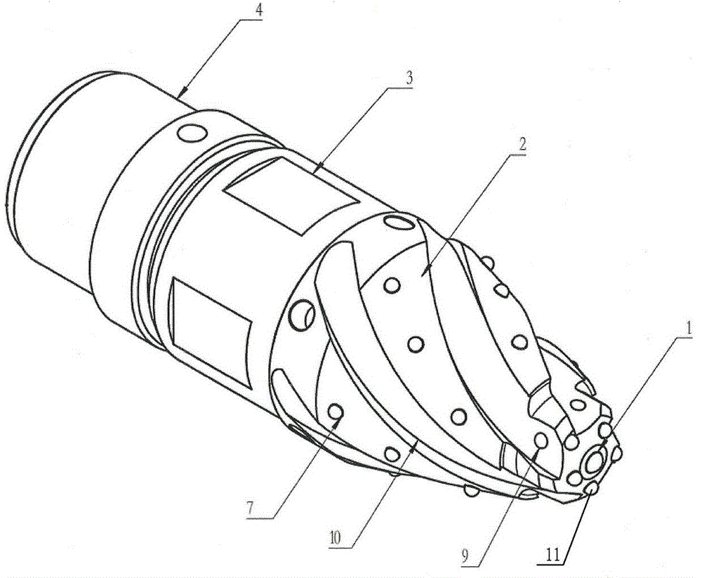
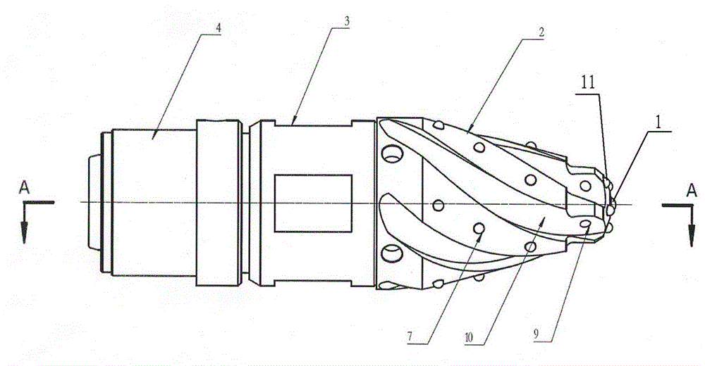
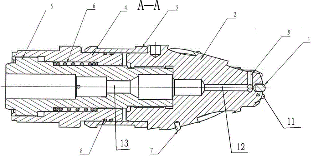
[0014] see figure 1 , figure 2 and image 3 Shown, the present invention is made of the first cemented carbide button 1, drill body 2, sealing cover 3, lower joint 4, anvil 5, return spring 6, the second carbide button 7, seal ring 8, the first Consisting of three carbide buttons 11, the inside of the drill bit body 2 has trapezoidal threads to connect with the anvil 5, the lower joint 4 is set on the anvil 5 and docked with the drill bit body 2, and the sealing cover 3 is set on the drill bit body 2 and the lower joint 4 Outer circumference, a sliding sealing ring 8 is set between the sealing cover 3 and the lower joint 4, the return spring 6 is located in the annular space formed by the anvil 5 and the lower joint 4, the first hard alloy button 1, the second hard alloy button The alloy button 7 and the third tungsten carbide button 11 are welded on the surface of the drill body 2, the first tungsten carbide button 1 is arranged at the center of the end of the drill body 2...


PUM


Abstract

The invention discloses a churn compaction drill bit which consists of a first hard alloy ball tooth, a drill bit body, a sealing cover, a lower joint, an anvil block, backsprings, second hard alloy ball teeth, sealing rings and third hard alloy ball teeth, wherein the drill bit body adopts a single-head or multi-head conical spiral cutting edge; the first hard alloy ball tooth, the second hard alloy ball teeth and the third hard alloy ball teeth are embedded and welded into the top end and the surface of a conical body; exhaust holes are formed in the bottom of the drill bit body along the radial direction and are used for cooling the edge teeth of the drill bit and the outer surface of the drill bit body; the anvil block and the drill bit body adopt a split type design and are connected with each other through trapezoidal threads to well meet a rotation working condition; the backsprings are used for quickly resetting the anvil block under a condition of no external load; the backsprings are matched with an impactor to keep a continuous counter impact working condition; the sealing cover is in interference fit with the drill bit body and is welded with the drill bit body; the fluororubber sealing rings are arranged between the sealing cover and the lower joint. The churn compaction drill bit can be matched with an impact spear to realize churn compaction drilling, is generally suitable for stratums such as a frozen earth layer, a sand layer and a sandy gravel layer and can achieve higher drilling efficiency and high drilling quality.

Description

technical field [0001] The invention relates to a compacting drill bit, in particular to a rotary compacting drill bit which cooperates with an impactor for impact rotary compaction drilling, and is applicable to strata such as frozen soil, sandy soil, sandy pebble layer and the like. Background technique [0002] Generally, the impact lance compacting hole forming technology is to apply an impact load to the drilled formation under the condition that the impact lance does not rotate, so as to realize drilling and forming holes. Compared with the impact lance compaction hole forming technology, the impact rotary compaction drilling technology not only applies impact force to the drill bit during the drilling process, but also applies rotational force to the drill bit. Under the joint action, the soil is squeezed into the formation, the drilling efficiency is high, and the drilling quality is good. The traditional impact compaction bit body only drills into the formation und...

Claims


Application Information

Patent Timeline
IPC IPC(8): E21B10/00E21B10/46
Inventor 孙友宏时元玲李梦王清岩高科常荣剑周康范帅朋王哲伟张雨
Owner JILIN UNIV
Why Eureka
Try Eureka