Non-contact electrification concealed wire recognizing device

An identification device, non-contact technology, applied in the direction of measurement device, electric/magnetic exploration, radio wave measurement system, etc., can solve the problem of inability to directly determine the location and direction of live cables, and inability to directly confirm whether the cable is live, metal detection method Use restrictions and other issues to achieve the effect of large security

Active Publication Date: 2014-02-05
JIANGSU TONGCHI POWER AUTOMATION
View PDF6 Cites 4 Cited by
  • Summary
  • Abstract
  • Description
  • Claims
  • Application Information

AI Technical Summary

Problems solved by technology

[0002] There are many methods for dark line measurement, mainly the following two: 1 Metal detection method: The measurement method based on the metal detection principle has been perfected, and it is not possible to directly confirm whether the cable is charged during the test
2. Wave injection method: use the signal loop principle to inject test signals into the cable, and judge whether there is a cable at other positions based on the detected signal strength. This type of method includes indirect coupling and direct coupling. Direct coupling requires power-off detection. Due to the influence of the signal radiation range, it is usually impossible to directly determine the position and direction of the live cable
In the actual power engineering construction, it is usually encountered that the position and direction of the live cable are detected continuously, and the use of the wave injection method and the metal detection method is limited.

Method used


Image

  • Non-contact electrification concealed wire recognizing device
  • Non-contact electrification concealed wire recognizing device
  • Non-contact electrification concealed wire recognizing device

Examples


Embodiment

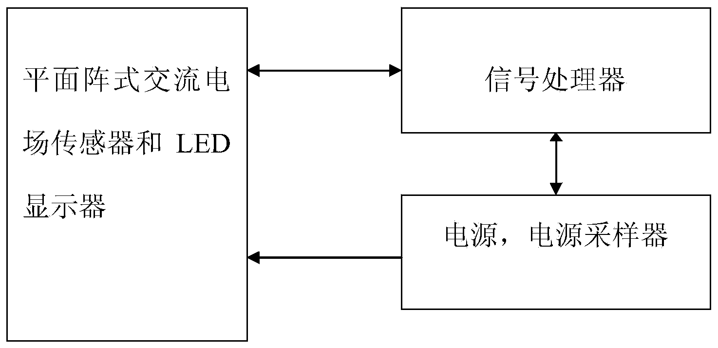
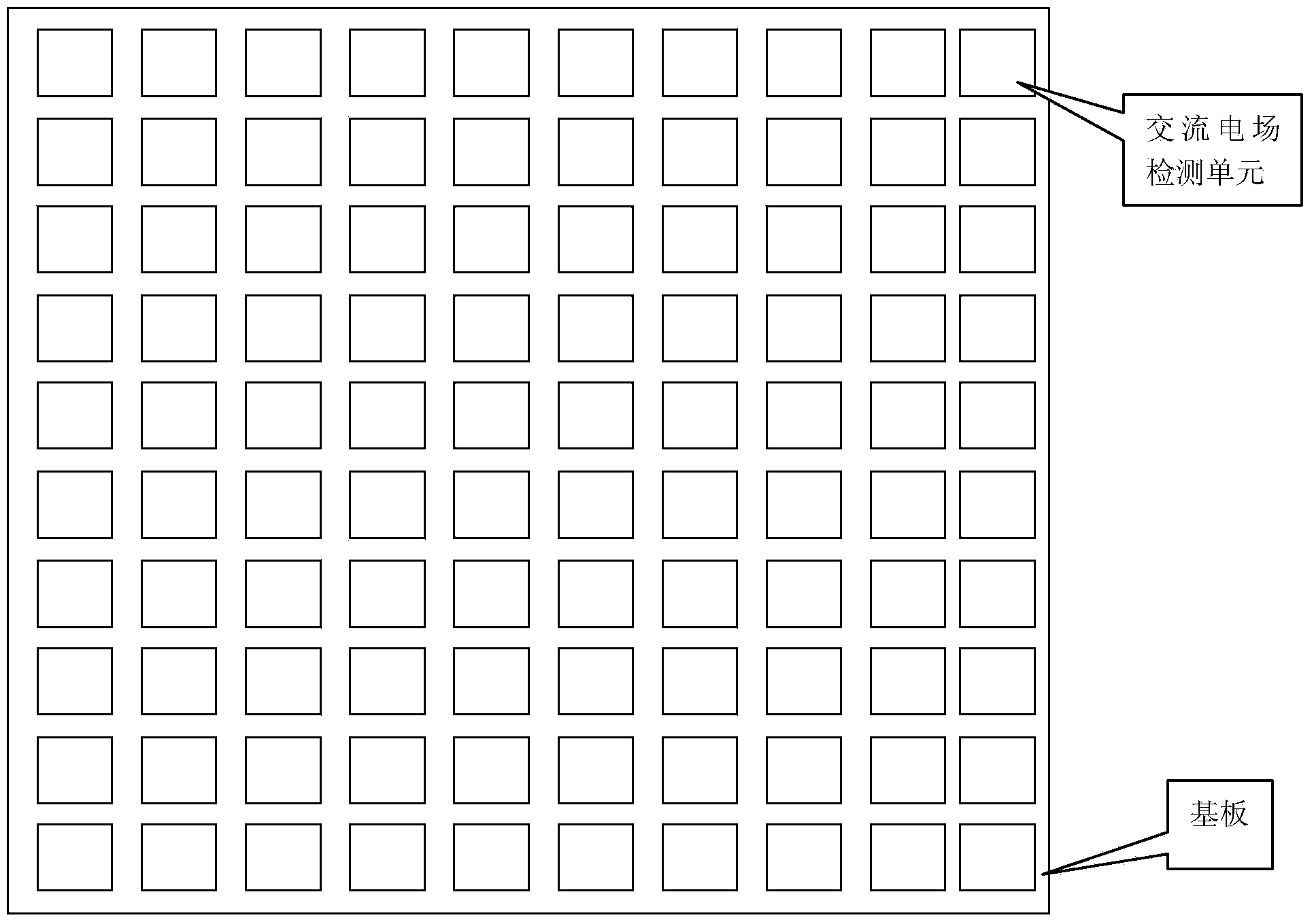
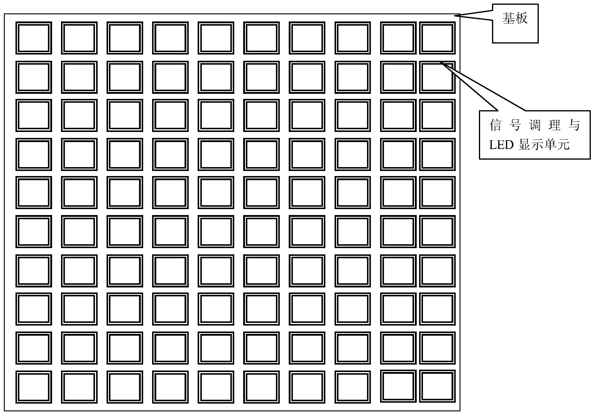
[0017] see figure 1 , The example of the present invention consists of an AC electric field detection unit, a signal processing unit, a hidden line position identification unit, etc., and a power supply. Among them, the AC electric field detection unit is a surface array sensor, which senses the distribution of the AC electric field on a sensing plane, and the vector size of the electric field is proportional to the induced voltage at both ends of the capacitor. The impact of measurement; in order to reduce the impact of transmission on the voltage across the capacitor, there is a signal conditioning circuit behind each detection unit to output the signal with low impedance. The signal processing unit scans the induction signal detected by the AC electric field, performs coherent processing on the signal through the A / D sampling circuit and the signal processor, analyzes the component in phase with the power supply connected to the device, and issues an instruction to light up...


PUM


Abstract

The invention discloses a non-contact electrification concealed wire recognizing device. The non-contact electrification concealed wire recognizing device comprises alternating current electric field detecting units, signal processing units and concealed wire position recognizing units, the alternating current electric field detecting units are of a plane array type structure, namely, the alternating current electric field detecting units are placed on a plane in an array mode, each electric field detecting unit is connected with one signal conditioning unit, the signal processing units receive output signals of the signal conditioning units to scan a plane array periodically and carry out coherent processing on known open wire signals, then the position of an electrification alternating current wire is judged, the concealed wire position recognizing units receive the position information of the signal processing units, and accordingly the position information of an electrification concealed wire is displayed. The electrification concealed wire is measured through an array sensor, coherent processing is carried out on the signals, and the effect on the measuring result from the outside electromagnetic interference is avoided. Meanwhile, the position and the direction of the electrification concealed wire can be accurately displayed through a plane array type display unit, and a safety guarantee is brought to power construction.

Description

technical field [0001] The invention relates to an identification device applied to hidden live wires, in particular to an identification device capable of identifying live cables buried in other non-metallic shielding objects. Background technique [0002] There are many ways to measure dark wires, mainly the following two: 1 Metal detection method: The measurement method based on the principle of metal detection has been perfected, and it is not possible to directly confirm whether the cable is live during the test. 2. Wave injection method: use the signal loop principle to inject test signals into the cable, and judge whether there is a cable at other positions based on the detected signal strength. This type of method includes indirect coupling and direct coupling. Direct coupling requires power-off detection. Due to the influence of the signal radiation range, it is usually impossible to directly determine the position and direction of the live cable. The direct measur...

Claims


Application Information

Patent Timeline
Patent Type & Authority Applications(China)
IPC IPC(8): G01V3/08
Inventor 陈二利
Owner JIANGSU TONGCHI POWER AUTOMATION
Why Eureka
Try Eureka