Spanner for replacing 500-kV circuit spacer

A line interval and wrench technology, applied in the direction of wrenches, overhead line/cable equipment, wrenches, etc., can solve the problems of slow replacement, bulky and cumbersome, inconvenient operation, etc., and achieves weight reduction, volume reduction, convenient and labor-saving operation Effect

Active Publication Date: 2014-02-05
LIVE WORKING CENT OF STATE GRID HUNAN ELECTRIC POWER +2
View PDF4 Cites 2 Cited by
  • Summary
  • Abstract
  • Description
  • Claims
  • Application Information

AI Technical Summary

Problems solved by technology

However, the wrenches used to replace spacers have the disadvantages of being bulky, inconvenient to carry, inconvenient to operate, and slow to replace.

Method used


Image

  • Spanner for replacing 500-kV circuit spacer
  • Spanner for replacing 500-kV circuit spacer
  • Spanner for replacing 500-kV circuit spacer

Examples


Embodiment Construction

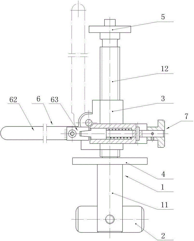
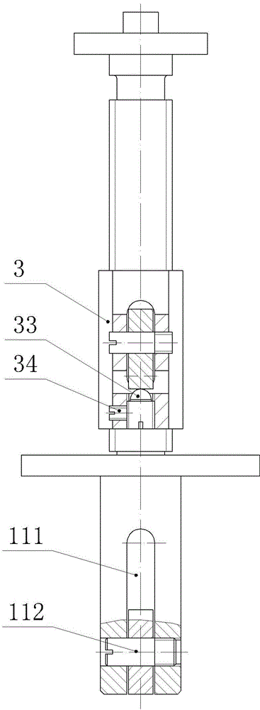
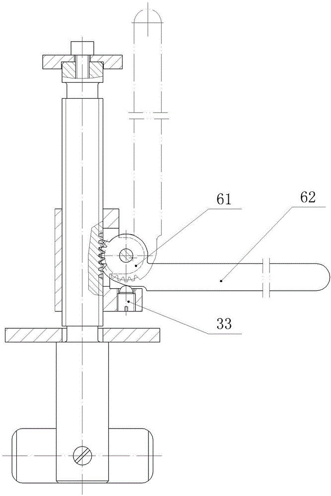
[0021] like Figure 1 to Figure 8 As shown, the wrench used to replace the 500kV line spacer provided by the present invention includes a screw rod 1, one end of which is a cylindrical rod 11 and the other end is a threaded rod 12, the diameter of the cylindrical rod 11 is greater than the diameter of the threaded rod 12, and the cylindrical rod 11 There is a rotatable pressing plate 2 in the axial center of the outer end of the outer end, which is used to compress the movable snap ring of the clamp of the spacer rod. The washer 4 is located between the cylindrical rod 11 and the moving seat 3, and the outer end of the threaded rod 12 has a retaining ring 5 for limiting the moving seat 3; the moving seat 3 is connected with a handle 6 and a locking member 7 for positioning the handle 6, The front end of the handle assembly 6 is a cam 61 , and the cam 61 has teeth engaged with threads on the threaded rod 12 for realizing the movement of the moving base 3 around the threaded rod...


PUM


Abstract

The invention discloses a spanner for replacing a 500-kV circuit spacer. The spanner for replacing the 500-kV circuit spacer comprises a screw. One end of the screw is a cylindrical rod and the other end of the screw is a threaded rod. The diameter of the cylindrical rod is larger than that of the threaded rod. The center of the outer end of the cylindrical rod in the axial direction is provided with a compressing board capable of rotating. The threaded rod is provided with a moving base and a circular gasket which are capable of moving in the longitudinal direction of the threaded rod. The circular gasket is located between the cylindrical rod and the moving base. The outer end of the threaded rod is provided with a check ring capable of limiting the moving base. The moving base is connected with a handle component and a locking element capable of locating the handle component. The front end of the handle component is a cam. The cam is provided with gear teeth meshed with threads on the threaded rod and used for enabling the moving base to rotate around the threaded rod. According to the spanner for replacing the 500-kV circuit spacer, the position of the moving base is rapidly adjusted through the method that the moving base slides along the threaded rod, the handle component is locked on the moving base through the locking element, the moving base rotates around the threaded rod through the method that the cam at the front end of the handle component is meshed with the threads on the threaded rod, so that the position of the moving base is rapidly adjusted, and the operation time is greatly shortened.

Description

technical field [0001] The invention relates to a wrench for replacing a 500kV line spacer. Background technique [0002] At present, 220kV and 330kV transmission lines use two-split conductors, 500kV transmission lines use four-split and six-split conductors, and ultra-high voltage transmission lines with voltages higher than 500kV use eight-split and more split conductors. In order to ensure that the spacing between the split wire harnesses remains unchanged to meet the electrical performance and ensure the flow capacity, spacers are installed at a certain distance in the span. Installing the spacer can also play a certain role in restraining the vibration of the wire and the breeze vibration. But the wrench for changing the spacer has the disadvantages of being bulky, heavy, inconvenient to carry, inconvenient to operate, and slow in replacement speed. Contents of the invention [0003] The purpose of the present invention is to provide a wrench capable of quickly rep...

Claims


Application Information

Patent Timeline
Patent Type & Authority Applications(China)
IPC IPC(8): H02G1/02B25B13/48
Inventor 郑克全刘夏清夏增明李智慧龙朴忠雷冬云彭金刚喻辉向云刘治国
Owner LIVE WORKING CENT OF STATE GRID HUNAN ELECTRIC POWER
Why Eureka
Try Eureka