Cable test controller based on can bus communication
A CAN bus, test controller technology, applied in line transmission monitoring/testing, electrical components, line transmission components and other directions, can solve problems affecting the accuracy of test results and other issues
- Summary
- Abstract
- Description
- Claims
- Application Information
AI Technical Summary
Problems solved by technology
Method used
Image
Examples
specific Embodiment approach 1
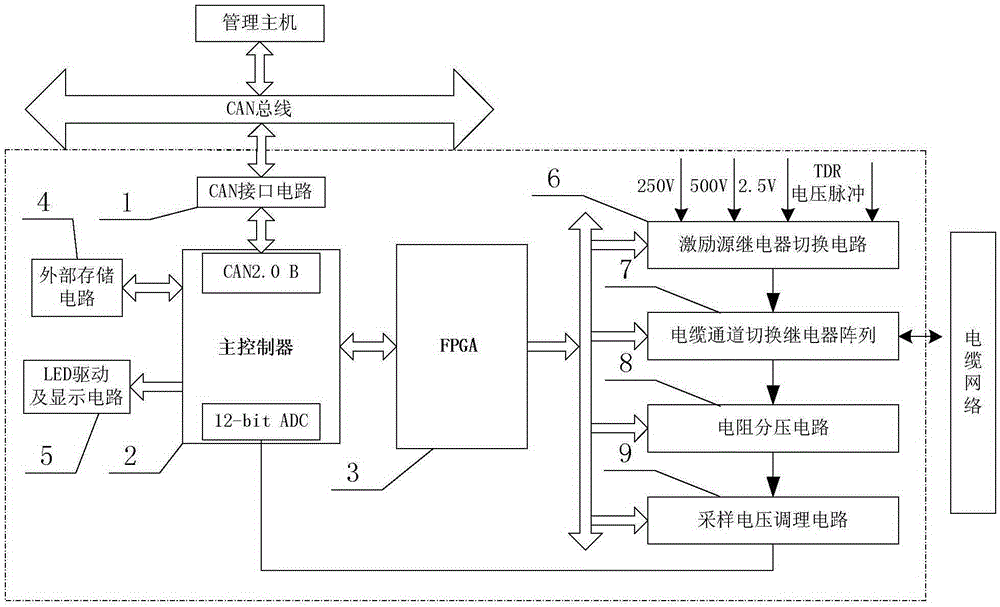
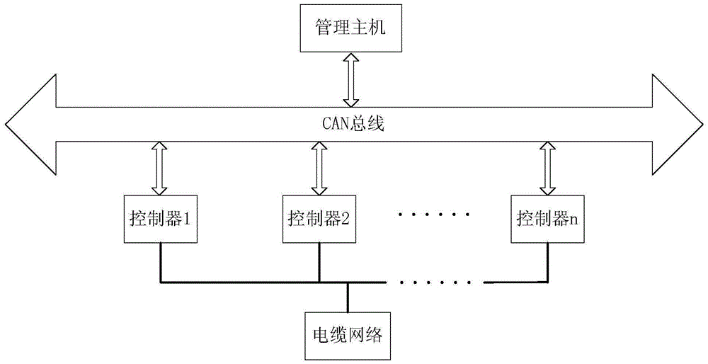
[0068] Specific implementation mode one: the following combination figure 1 and figure 2 Describe this embodiment, the cable test controller based on CAN bus communication described in this embodiment, the test controller realizes the communication with the management host through the CAN bus, and the test controller is connected to the cable network through an adapter cable; The test controller includes CAN interface circuit 1, main controller 2, FPGA3, external storage circuit 4, LED drive and display circuit 5, excitation source relay switching circuit 6, cable channel switching relay array 7, resistance voltage divider circuit 8 and sampling voltage conditioning circuit 9,
[0069] The CAN interface circuit 1 is an interface circuit between the CAN bus and the main controller 2, and is used to realize the level conversion between the node logic level and the CAN bus differential level;
[0070] The main controller 2 realizes data interaction with the management host, an...
specific Embodiment approach 2
[0086] Embodiment 2: This embodiment further describes Embodiment 1. The main controller 2 in this embodiment is realized by using a DSP2812 chip.
specific Embodiment approach 3
[0087] Specific implementation mode three: the following combination image 3 Describe this embodiment, this embodiment will further explain Embodiment 2, the reset logic of the FPGA3 described in this embodiment adopts two reset modes of power-on reset and button reset, and the power-on reset mode is divided into RC circuit reset and logic reset;
[0088] Described RC circuit reset adopts counter module to realize, after main controller 2 is powered on, counter module receives clock signal clk-dsp and starts counting, and the output end / rs of counter module outputs low level now; When the counting time of counter module After reaching the time required for the reset of the main controller 2, the counter module stops counting, and / rs outputs a high level; the level signal / RS1 output by the output terminal / rs of the counter module is used as a reset signal of AND logic;
[0089] The logic reset signal / RS2 is used as the second reset signal of AND logic;
[0090] The reset ...
PUM
 Abstract
Description
Claims
Application Information
 - R&D
- Intellectual Property
- Life Sciences
- Materials
- Tech Scout
- Unparalleled Data Quality
- Higher Quality Content
- 60% Fewer Hallucinations
Browse by: Latest US Patents, China's latest patents, Technical Efficacy Thesaurus, Application Domain, Technology Topic, Popular Technical Reports.
© 2025 PatSnap. All rights reserved.Legal|Privacy policy|Modern Slavery Act Transparency Statement|Sitemap|About US| Contact US: help@patsnap.com


