

Planar heat-generating body and method for manufacturing same
A manufacturing method and heating element technology, applied in the direction of electric heating devices, ohmic resistance heating, heating element materials, etc., to achieve good defogging performance, suppression of electrical conductivity reduction, and long-term good heating performance
- Summary
- Abstract
- Description
- Claims
- Application Information
AI Technical Summary
Problems solved by technology
Method used
Image

Examples
Embodiment 1
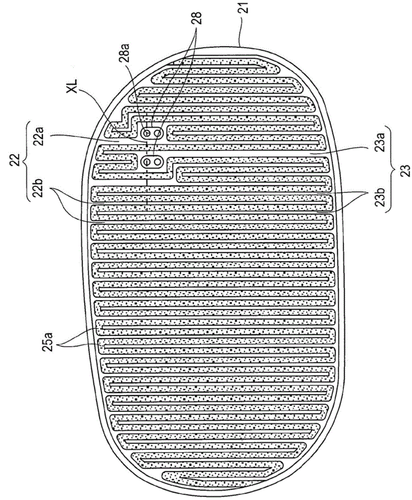
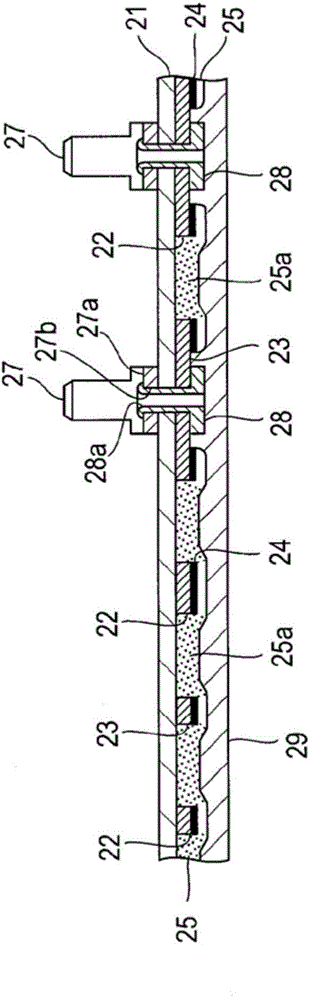
[0042] A planar heating element test piece was produced in the following manner. After heat-bonding the aluminum foil with a hot-melt adhesive to the base film 21 made of polyester film, the aluminum foil was peeled off with a cutter to form electrode patterns (electrodes 22 and 23 ). The main electrodes 22a, 23a have a width of 3 mm, and the comb-shaped electrodes 22b, 23b have a width of 1 mm. Next, a conductive paste obtained by kneading carbon black and graphite powder in phenol resin was screen-printed on the electrodes 22 and 23 , and heat-cured (150° C., 5 minutes to 10 minutes) to form the conductive coating 24 . The thickness of the conductive film 24 is 10 μm. The resistivity of the conductive coating 24 at this time was 0.2 Ω·cm. Then, the PTC heating element paste (resistivity: 50 Ω·cm) was printed to form the PTC heating element film 25, the terminals 27 for energization were installed, and the double-sided adhesive tape 29 was attached to complete the planar he...
Embodiment 2
[0046] Two planar heating element test pieces were produced in the following manner. The electrode patterns and the conductive film 24 of the two test pieces were formed by the same procedure as in Example 1. The resistivities of the conductive coatings 24 of the two test pieces were 0.02 Ω·cm and 20 Ω·cm, respectively, and the total film thickness was 10 μm. The PTC heating element paste (resistivity: 50 Ω·cm) was printed, and two planar heating element test pieces were completed through the same process as in Example 1. The resistance values between terminals 27 are 15.8Ω and 31.0Ω, respectively.
[0047] These planar heating element test pieces were placed in the same high-temperature and high-humidity state as in Example 1, and the resistance value after 72 hours was measured. The resistance value measurement results were 1.02 times and 1.05 times, respectively, which were values that hardly changed from the initial state.
[0048] In addition, the same temperature ...
Embodiment 3
[0050] Two planar heating element test pieces were produced in the following manner. The electrode patterns and the conductive film 24 of the two test pieces were formed by the same procedure as in Example 1. The film thicknesses of the conductive coatings 24 of the two test pieces were 5 μm and 70 μm, respectively, and the total resistivity was 0.2 Ω·cm. The PTC heating element paste (resistivity: 50 Ω·cm) was printed, and two planar heating element test pieces were completed through the same process as in Example 1. The resistance values between terminals 27 are 16.52Ω and 15.64Ω, respectively.
[0051] The same temperature cycle test as in Example 1 was implemented on these planar heating element test pieces. The resistance value was measured after five cycles, and it became 0.98 times and 1.02 times, respectively, showing little change.
PUM
 Abstract
Description
Claims
Application Information