A high shear dispersing emulsifier

A high-shear, emulsifier technology, used in mixers, mixer accessories, chemical instruments and methods, etc., can solve the problems of inability to complete online production, wide particle size distribution range, large particle size, etc., and achieve good shearing effect. , Increase the shearing time and improve the effect of dispersion

Active Publication Date: 2016-06-29
PUHLER GUANGDONG SMART NANO TECH CO LTD
View PDF6 Cites 1 Cited by
  • Summary
  • Abstract
  • Description
  • Claims
  • Application Information

AI Technical Summary

Problems solved by technology

However, the disadvantage of this emulsifier is that the stator and rotor are single-stage, the particle size after the material is dispersed and emulsified is relatively large, and the particle size distribution range is wide, and the product uniformity is not good; there is also a dispersing emulsification equipment, which includes constant The rotor assembly and the reactor, different types of liquids are placed in the reactor in advance, and then the motor drives the main shaft to drive the rotor of the stator and rotor assembly to rotate, and finally the different types of liquids are evenly dispersed and emulsified in the reactor
The disadvantage of this kind of emulsifier is that the processed materials are produced in batches, and online production cannot be completed, which may easily cause quality differences between batches; and the stator and rotor are single-stage, the particle size of the material after dispersion and emulsification is relatively large, and the particle size distribution is relatively large. The range is wide, and the product uniformity is not good; there is also a stirring equipment, which is mainly composed of a transmission shaft, a stirring paddle and a reactor. Different types of liquids are placed in the reactor in advance, and then the motor drives the shaft to drive the paddles to rotate, and finally Disperse and mix different kinds of liquids in a reactor
The disadvantage is that the blades cannot shear the particle size of the liquid, the emulsification effect is not good, and the efficiency is low

Method used


Image

  • A high shear dispersing emulsifier
  • A high shear dispersing emulsifier
  • A high shear dispersing emulsifier

Examples


Embodiment Construction

[0029] Describe the present invention in detail below in conjunction with accompanying drawing:

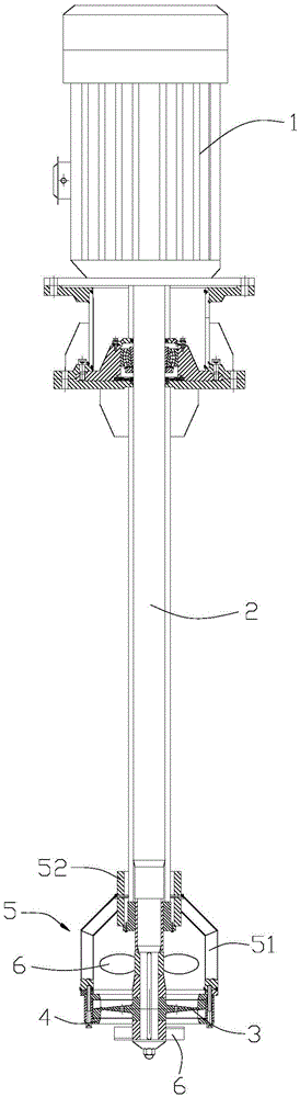
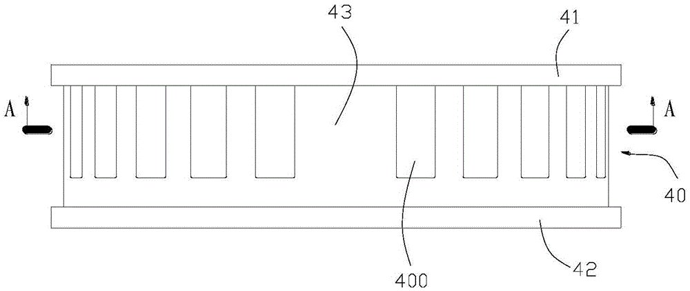
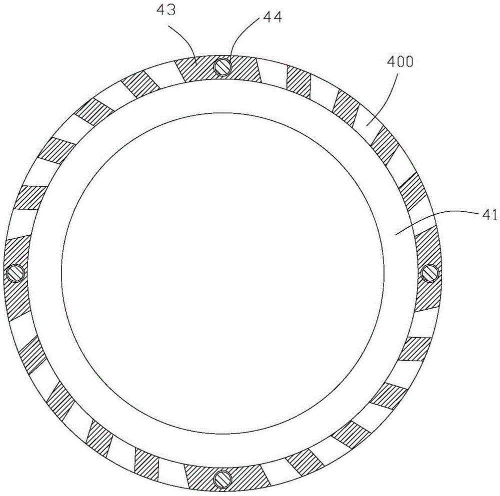
[0030] figure 1 , figure 2 , image 3 , Figure 4 , Figure 5 It shows a high-shear dispersing emulsifier, which includes a vertical main shaft 2 connected to a motor 1 at the upper end, and the motor can directly clamp the main shaft through a clamp to drive its rotation. This method has a simpler structure and a smaller volume of the emulsifier , can also use coupling, belt drive to drive the main shaft, this way of transmission is more stable. A rotor 3 is connected to the lower end of the main shaft, and a stator 4 is mounted on the outer periphery of the rotor. The stator is fixed by a bracket 5 arranged between the upper and lower ends of the main shaft. The bracket adopts the first structure, such as figure 1 , which includes a shaft sleeve 51 sleeved on the lower part of the main shaft, and several support rods 52 are arranged between the shaft sleeve and the stator....


PUM


Abstract

The invention relates to material refining equipment, in particular to a high shear dispersion emulsifying machine. The high shear dispersion emulsifying machine comprises a vertical main shaft connected with a motor at the upper end, wherein the lower end of the main shaft is connected with a rotor; a stator is fitted and mounted on the periphery of the rotor, and is fixed through a bracket arranged on the main shaft and between the lower ends; at least one circle of fixed tooth ring is formed on the stator; tooth grooves of each circle of fixed tooth ring are inclined grooves; the rotor is provided with at least one circle of movable tooth ring correspondingly; tooth grooves of each circle of movable tooth ring are straight grooves; each circle of movable tooth ring is sleeved on the inner side of corresponding fixed tooth ring at radial intervals. Under the high-speed driving of the motor, materials move with high speed in a narrow gap between the rotor and the stator to form turbulent flows, so that effects of dispersion, emulsification and crushing can be achieved, and excellent material foundation is provided for subsequent grinding procedure; at the same time, as the fitting manner of stator as the inclined groove and the rotor as the straight groove is adopted, the material shearing time is improved, and the better shearing effect is achieved.

Description

technical field [0001] The invention relates to material refinement equipment, in particular to a dispersing and emulsifying machine. Background technique [0002] At present, the dispersing and emulsifying machine has different kinds of liquids or mixtures of liquid and solids in advance at the feeding port, and then the motor drives the main shaft to drive the rotor to rotate, and finally different kinds of liquids or mixtures of liquids and solids are dispersed and emulsified in the working chamber. However, the disadvantage of this emulsifier is that the stator and rotor are single-stage, the particle size after the material is dispersed and emulsified is relatively large, and the particle size distribution range is wide, and the product uniformity is not good; there is also a dispersing emulsification equipment, which includes constant The rotor assembly and the reactor, different types of liquids are placed in the reactor in advance, and then the motor drives the main ...

Claims


Application Information

Patent Timeline
Patent Type & Authority Patents(China)
IPC IPC(8): B01F7/16B01F3/08B01F15/00B01J19/18
Inventor 雷立猛
Owner PUHLER GUANGDONG SMART NANO TECH CO LTD
Why Eureka
Try Eureka