Rear steel moving push plate of cogging mill

A billet opening machine and push plate technology, applied in metal processing equipment, metal rolling, manufacturing tools, etc., can solve the problems of steel material bending to the left, easy to deviate from the rolling center line, etc., to achieve smooth operation and easy layout , Low production and installation costs

Inactive Publication Date: 2014-02-12
WUHU XINXING DUCTILE IRON PIPES
View PDF6 Cites 0 Cited by
  • Summary
  • Abstract
  • Description
  • Claims
  • Application Information

AI Technical Summary

Problems solved by technology

However, when rolling large-size billets, the pusher at the back of the machine cannot move the steel accurately because the steel is too long. It can only effectively clamp the front part of the steel, and the rear part of the steel cannot be clamped by the pusher and moves to the left. The bending is serious, which makes the steel material easily deviate from the rolling center line during the rolling process, resulting in various process accidents such as torsion and flat steel

Method used


Image

  • Rear steel moving push plate of cogging mill
  • Rear steel moving push plate of cogging mill

Examples


Embodiment Construction

[0019] The specific implementation of the present invention will be described in further detail below by describing the embodiments with reference to the accompanying drawings, so as to help those skilled in the art have a more complete, accurate and in-depth understanding of the inventive concepts and technical solutions of the present invention.

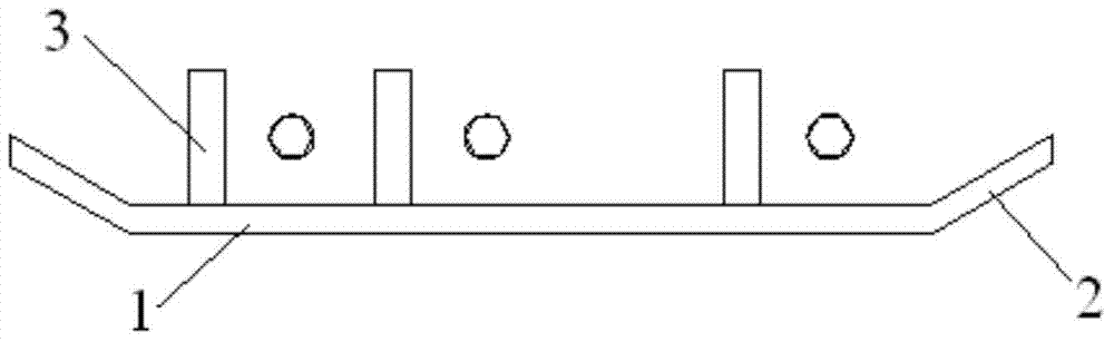
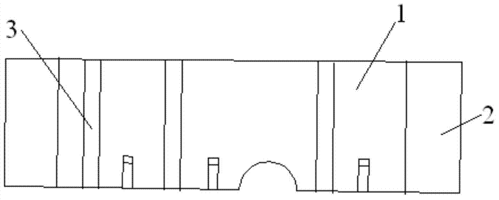
[0020] Such as figure 1 , figure 2 The shown structure of the present invention is the push plate 1 for moving the steel back of the billet breaker, and is used for the billet breaker to roll large-size billets.

[0021] In order to solve the problems existing in the prior art and overcome its defects, and realize the invention purpose of preventing the steel material from twisting and falling steel accidents, the technical scheme adopted by the present invention is:

[0022] Such as figure 1 , figure 2 As shown, the two ends of the push plate 1 of the present invention are provided with bends 2, and the bending direction of t...


PUM


Abstract

The invention discloses a rear steel moving push plate of a cogging mill, and the rear steel moving push plate is used for rolling large-size blanks by the cogging mill. Bends (2) are arranged at the two ends of a push plate (1); the bending direction of the bends (2) is opposite to a steel pushing direction. According to the technical scheme, the push plate is compact in structure, easy to arrange, high in driving force, easy to replace and maintain and resistant to wear due to unique structure; the rear push plate and a push machine have the same running speed and stable running and accurate speed and position control of the push plate are realized through coupling of the push plate and a push machine; the push plate is very suitable for blanks with increasing sizes and lengths; the big difficult problem of steel moving after the cogging mill is radically solved; more importantly, the manufacturing and mounting costs of the push plate are very low, so that the production cost is saved.

Description

technical field [0001] The invention belongs to the technical field of production equipment in the metallurgical industry, and relates to the technology of steel rolling production equipment. More specifically, the invention relates to a steel push plate that is moved backward by a blanking machine. Background technique [0002] In order to improve the output and quality of rolled steel products, many high-speed wire rod production lines, bar production lines and section steel production lines adopt large-scale continuous casting slabs, and automatically reciprocate rolling through billet opening machines with high rolling precision, large torque and large compression ratio. , to obtain the best rolled billet (or finished product), and finally send the billet to the continuous rolling mill for continuous rolling, and roll out the required wire rod, bar or section steel. [0003] When rolling large-size blanks, the pusher behind the blanking machine cannot move the steel smoo...

Claims


Application Information

Patent Timeline
Patent Type & Authority Applications(China)
IPC IPC(8): B21B39/02
Inventor 任毅
Owner WUHU XINXING DUCTILE IRON PIPES
Why Eureka
Try Eureka